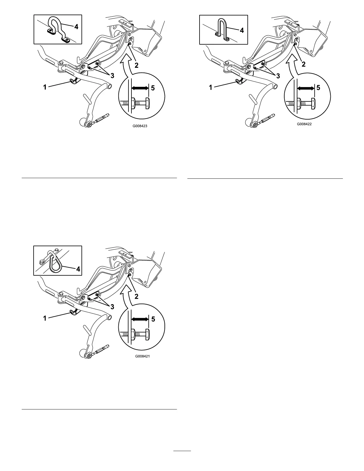
g008423
Figure13
1.Transportplate
4.Offsetlifthook
2.Adjustingscrew
5.25mm(1inch)
3.Transport-platemounting
screw
3.Oncuttingunitsequippedwithachainlinkor
astraightlifthook(Figure14andFigure15
insets),verifythatthedistancefromthetopof
thecarrierframeadjustingscrewtotheback
ofthecarrierframeis22mm(7/8inch).Ifthe
distanceisnot22mm(7/8inch),proceedtostep
4.Ifthecuttingunitisequippedwithanoffsetlift
link(Figure13),proceedtothenextstep.
g008421
Figure14
1.Transportplate
4.Chainlink
2.Adjustingscrew
5.22mm(7/8inch)
3.Transport-platemounting
screw
g008422
Figure15
1.Transportplate4.Linkhook
2.Adjustingscrew
5.22mm(7/8inch)
3.Transport—latemounting
screw
4.Loosenthetransportplatemountingscrews
(Figure14,Figure15,andFigure13).
5.Raisethecuttingunitstothetransportposition.
Important:Donotraisethesuspensionto
thetransportpositionwhenthereelmotors
areinthemachine-frameholders.Damage
tothemotorsorhosescouldresult.
6.Ensurethateachcarrierframeisatthesame
heightfromtheground.Iftheyare,proceedto
step8.
7.Ifthecarrierframesarenotatthesameheight,
loosenthejamnutonthecarrierframeadjusting
screw(Figure13,Figure14,andFigure15).
Rotatethescrewoutwardtoraiseandinwardto
lower.Tightenthejamnutafteryouobtainthe
properheight.
8.Rotatethetransportplateuntilitlocksthepull
frame.Tightenthescrews.
16

 Loading...


