Piston(traction)Pump
g350536
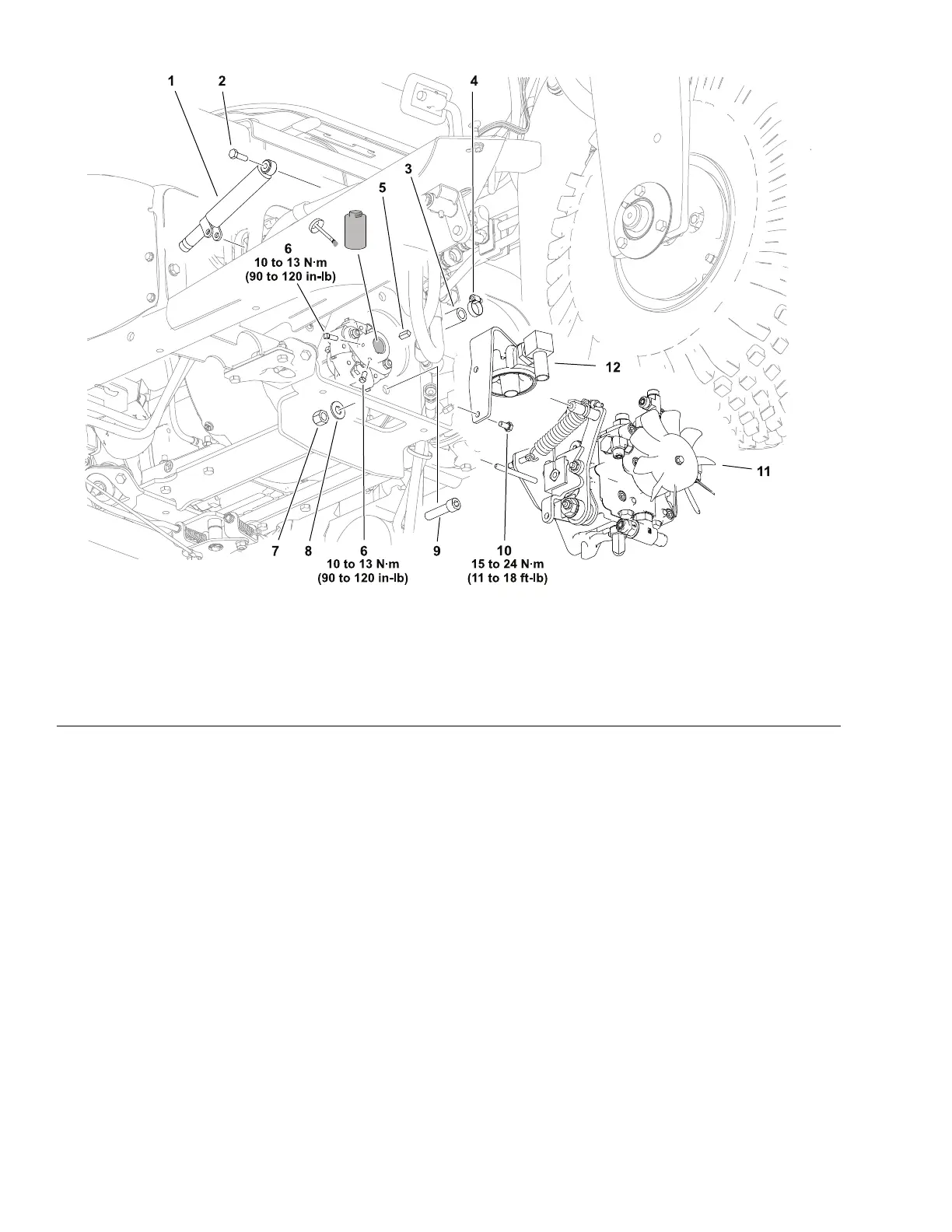
Figure51
1.Damper5.Key
9.Capscrew(2each)
2.Capscrew6.Setscrew(2each)10.Capscrew(2each)
3.Hydraulichose–lter7.Locknut(2each)11.Piston(traction)pumpassembly
4.Hoseclamp
8.Washer–hardened(2each)12.Hydraulicuidlterassembly
RemovingthePiston(traction)Pump
RefertoFigure51forthisprocedure.
1.Parkthemachineonalevelsurface,loweranyattachments,setthekey
switchtotheOFFpositionandremovethekeyfromtheswitch.
2.Removethecentershroud.
3.Placeadrainpanwithatleasta13.2liter(5gallon)capacityunderthe
hydraulicuidlterandremovethehydraulicuidlterfromthelterhead
todrainthehydraulictank.
4.Removethetractionrodassemblyanddiscardthecotterpin.
5.Disconnectthetractionneutralswitchconnectorfromthemachinewire
harness.
6.Removethetractioncontroldamper.
7.Removehydraulicuidcoolerfromthemachine;refertoRemovingand
InstallingtheHydraulicFluidCooler(page5–68).
8.ReadandadheretotheinformationprovidedinGeneralPrecautionsfor
RemovingandInstallingtheHydraulicSystemComponents(page5–54).
HydraulicSystem:ServiceandRepairs
Page5–70
SandPro
®
3040and5040
20251SLRevA

 Loading...