ServicingtheLiftControlValve
g351917
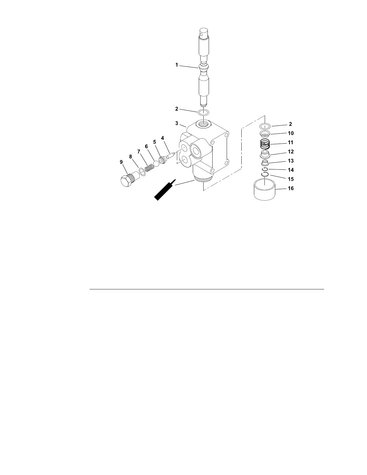
Figure61
1.Spool9.Plug(2each)
2.O-ring(2each)10.Springretainer,inner
3.Valvebody
11.Spring
4.Pin(2each)12.Springretainer,outer
5.Seat–valve(2each)13.Spacer
6.Ball(2each)
14.Retainingring,spool
7.Spring(2each)
15.Retainingring
8.O-ring(2each)16.Cap
Thesamevalveisusedforthestandardrearliftvalveandtheoptionalfrontlift
valve(kitmodelno08712).
DisassemblingtheLiftValve
RefertoFigure61forthisprocedure.
1.Washtheliftvalveinsolventanddrythoroughly
2.Carefullymounttheliftvalveinavisesothatthevalvemountingsurfaces
areagainstthejawsoftheviseandthecapoftheliftvalveisfacingupward.
3.Removethe2hexcapplugsfromthesideofthevalvebody.Removethe
spring,checkball,andcampinfrombehindeachhexcapplug.
4.Removethecheckballseats(item5)onlyiftheyneedreplacement;the
seatsarepresstintothevalvebody.
5.Carefullyremovethecap.
Note:Thecaphasalightpressttothevalvebody.
6.Removetheretainingring(item15).Removethespoolretainingring(item
14),outerspringretainer,spacer,spring,andtheinnerspringretainer.
HydraulicSystem:ServiceandRepairs
Page5–92
SandPro
®
3040and5040
20251SLRevA

 Loading...