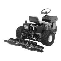
Figure9
1.Rearframeofthetraction
unit
2.Longlegofthelift-arm
assembly
4.Pivotthelockinglevertotherighttolocktheadapters
together.
4
AdjustingtheLinkAssembly
NoPartsRequired
Procedure
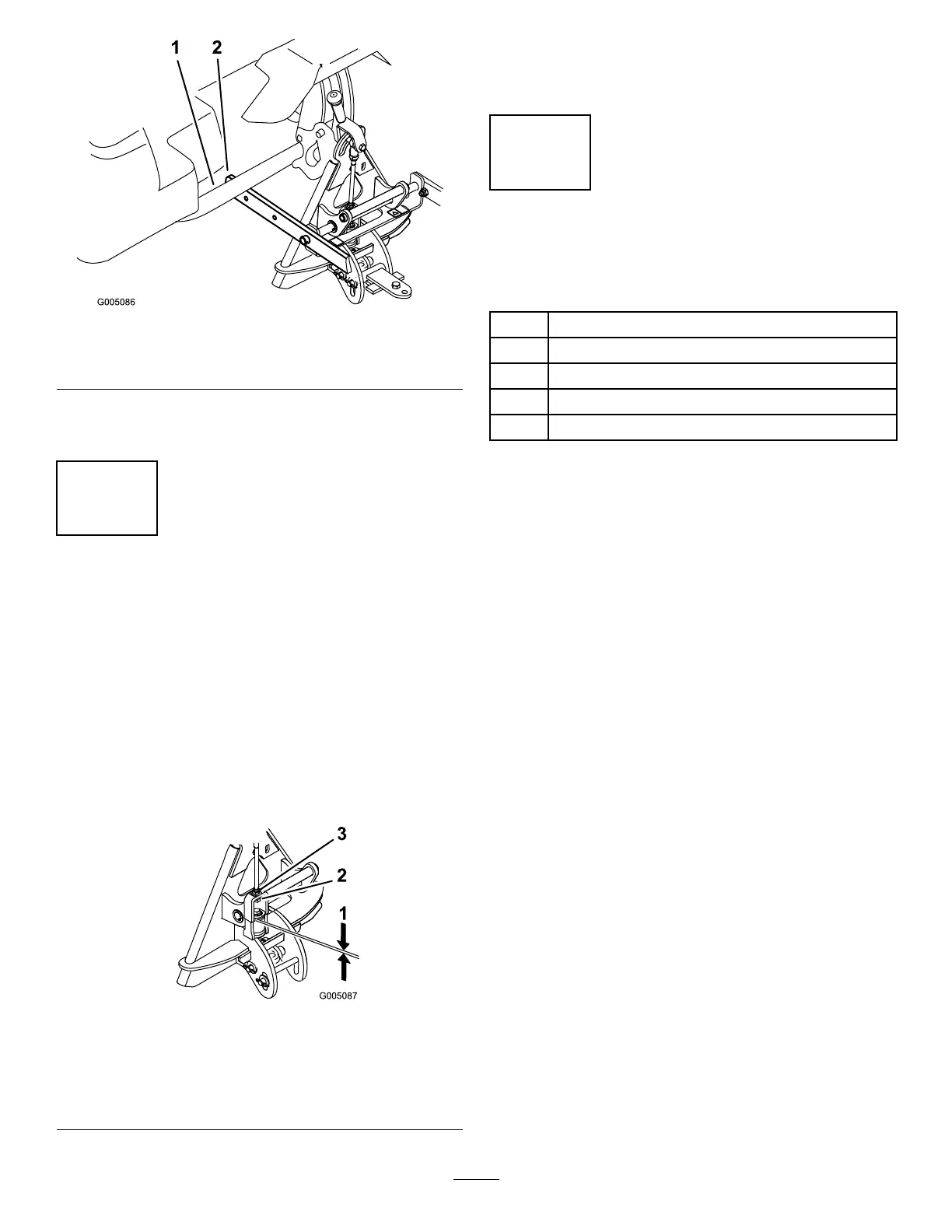
1.Withthedragmatmountedandsecuredonthetraction
unit,measurethegapbetweenthetopwasherandthe
spacerinthelinkassemblyontheattachmentadapter
asshowninFigure10.
Thegapbetweenthewasherandtheshouldershould
be1.5mmto2.0mm(0.060to0.080inch);referto
Figure10.
Figure10
1.1.5mmto2.0mm(0.060
to0.080inch)
3.Jamnut
2.Adjustmentnut
2.Ifthegapisnotcorrect,loosenthejamnutandtighten
orloosentheadjustmentnutonthelinkassemblyas
neededtochangethegap(Figure10).
5
ReadingtheDocumentation
andStoringtheLooseParts
Partsneededforthisprocedure:
1
Operator’sManual
1
PartsCatalog
1
Clevispin
1
Washer(0.469x0.922inch)
1Hairpincotter
Procedure
1.Readthedocumentation.
2.Storethedocumentationinasafeplace.
3.Storeanyloosepartsforusewhensecuringthe
side-to-sidepivot.
7

 Loading...