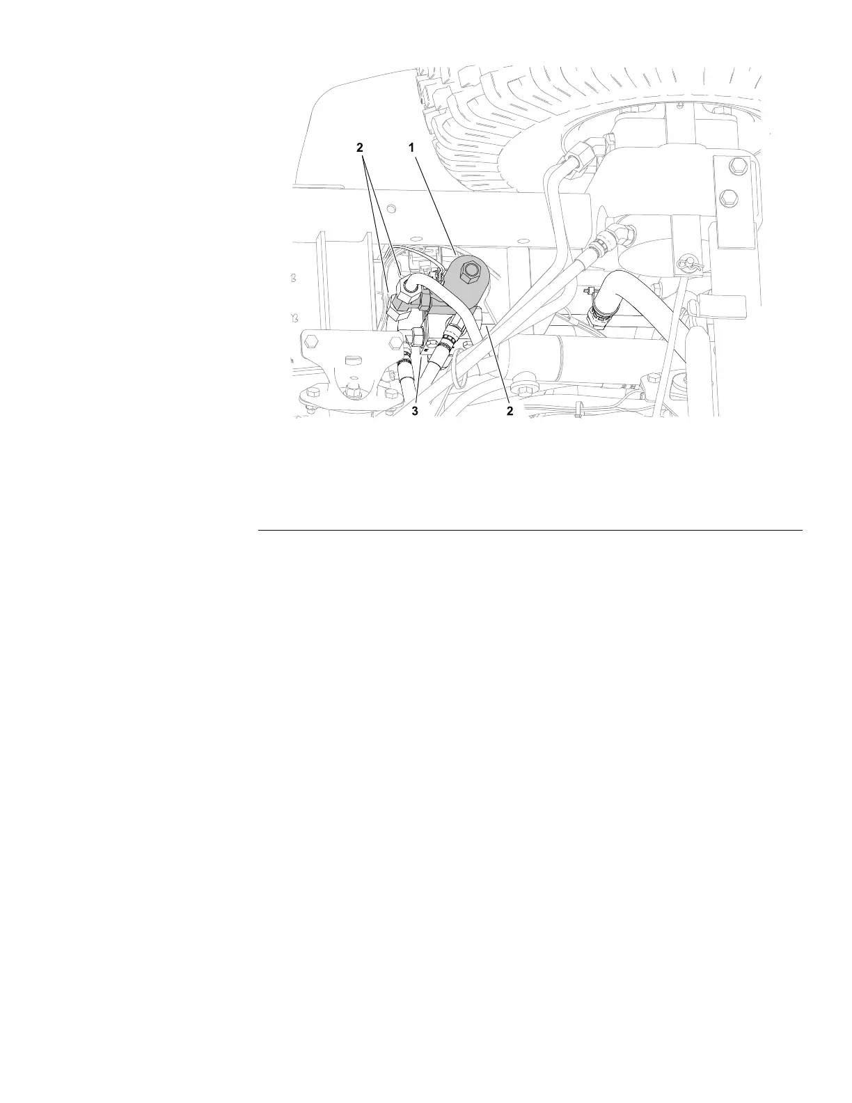
RearRemoteHydraulicsManifold(Optional)
g352948
Figure73
(viewfromundermachine)
1.Rearremotehydraulicsmanifoldassembly3.Tractionreliefmanifoldassembly
2.Hydraulictube(3each)
Therearremotehydraulicsmanifoldislocatedneartheleftrearwheel.
Forcartridgevalveserviceprocedures,refertoServicingaHydraulicCartridge
Valve(page5–87).
RemovingtheOptionalRearRemoteHydraulicsManifold
RefertoFigure73forthisprocedure.
1.Removetheleftrearwheel;refertoRemovingandInstallingtheRear
Wheels(page7–5).
2.Removetheleftsidewheelshroudandtheleftsidescreenpanel.
3.Disconnectthewireharnessfromtherearremotehydraulicssolenoidvalve
4.ReadandadheretotheinformationprovidedinGeneralPrecautionsfor
RemovingandInstallingtheHydraulicSystemComponents(page5–54).
5.Cleanthettingandhydraulictubeconnectionsbeforedisconnectingthe
hydraulictubestopreventsystemcontamination.
6.Labelallhydraulicconnectionsforassemblypurposesanddisconnectthe
hydraulictubes.
7.Capthettingsandplugthehydraulictubestopreventsystemcontamination.
8.Removethefastenerssecuringthetractionreliefmanifoldandtherear
remotehydraulicsmanifoldtothebracketandremovetherearremote
hydraulicsmanifoldassemblyfromthemachine.
9.Ifthehydraulicttingsaretoberemovedfromthemanifold,markthetting
orientationforassemblypurposesandremovethettingsfromthemanifold.
DiscardtheO-ringsfromthettings.
SandPro
®
3040and5040
Page5–115
HydraulicSystem:ServiceandRepairs
20251SLRevA
 Loading...