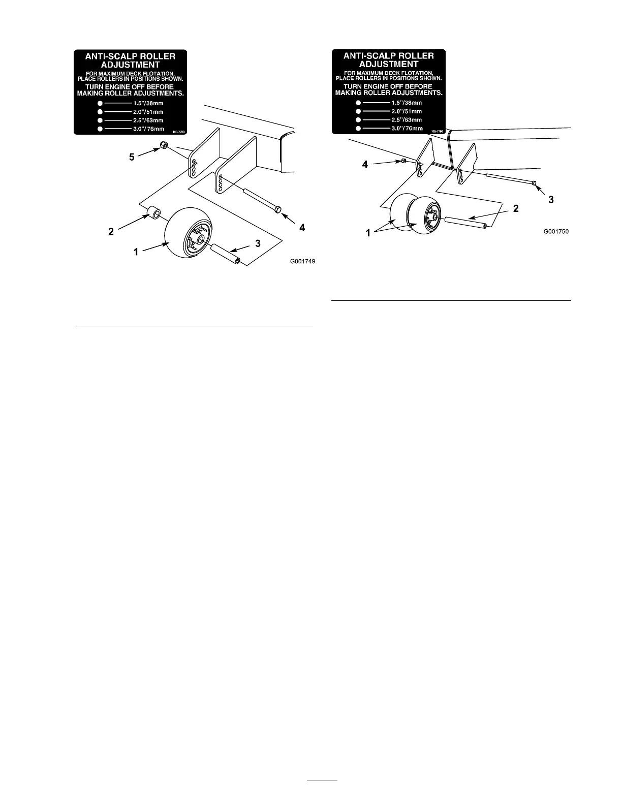
Figure 18
1. Outer roller 4. Bolt
2. Spacer
5. Nut
3. Bushing
4. Select a hole so that the outer roller is
positioned to the nearest cor responding
height-of-cut desired ( Figure 18 ).
5. Install the outer roller , bushing, spacer , bolt,
and n ut ( Figure 18 ).
6. T or que the bolt to 40 to 45 ft-lb (54 to 61
N ⋅ m).
Adjusting the Center Rollers
1. Diseng ag e the PTO , mo v e the motion control
lev ers to the neutral loc k ed position, and set
the parking brak e .
2. Stop the engine , remo v e the k ey , and w ait for
all mo ving par ts to stop before lea ving the
operating position.
3. After adjusting the height-of-cut, remo v e the
flang e n ut, bushing, and bolt ( Figure 19 ).
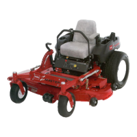
Figure 19
1. Outer roller 4. Bolt
2. Spacer
5. Nut
3. Bushing
4. Select a hole so that the center rollers are
positioned to the nearest cor responding
height-of-cut desired ( Figure 19 ).
Note: Do not adjust the rollers to suppor t
the mo w er housing .
5. Install the center rollers , bushing, spacer , bolt,
and n ut ( Figure 19 ).
6. T or que the bolt to 40 to 45 ft-lb (54 to 61
N ⋅ m).
Adjusting the Flow Bafe
T he mo w er disc harg e flo w can be adjusted for
different types of mo wing conditions . P osition the
cam loc ks and baffle to gi v e the best quality of cut.
1. Diseng ag e the PTO , mo v e the motion control
lev ers to the neutral loc k ed position and set
the parking brak e .
2. Stop the engine , remo v e the k ey , and w ait for
all mo ving par ts to stop before lea ving the
operating position.
3. T o adjust the cam loc ks , swing the lev er up to
loosen the cam loc k ( Figure 20 ).
4. Adjust the baffle and cam loc ks in the slots to
the desired disc harg e flo w .
5. Swing the lev er bac k o v er to tighten the baffle
and cam loc ks ( Figure 20 ).
6. If the cams do not loc k the baffle into place or
it is too tight, loosen the lev er and then rotate
23