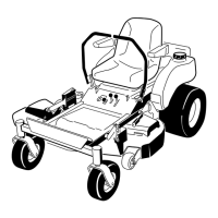
Figure 14
1. Control lever 3. Control arm shaft
2. Bolt
3. R e peat the adjustment for the opposite control
lev er .
Pushing the Machine by
Hand
Important: Al w ays push the machine by hand.
Nev er to w the machine because dama ge may
occur .
To Push the Machine
1. P ark the mac hine on a lev el surface and diseng ag e
the blade control (PTO).
2. Mo v e the motion control lev ers outw ard to eng ag e
the parking brak e , stop the engine , remo v e the k ey ,
and w ait for all mo ving par ts to stop before lea ving
the operating position.
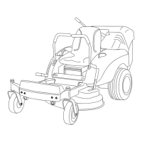
3. Raise the seat to access the b ypass lev ers
( Figure 15 ).
4. Mo v e the tw o b ypass lev ers forw ard and then
outw ard to loc k them in place as sho wn in
Figure 15 .
5. Mo v e the motion control lev ers inw ard to
diseng ag e the parking brak e .
T he mac hine is no w able to be pushed b y hand.
Figure 15
1. Bypass levers 3. Lever position for operating
the machine
2. Lever position for pushing
the machine
To Operate the Machine
Mo v e the b ypass lev ers to the inside and pull them
rearw ard, to the end the slot ( Figure 15 ).
Note: T he mac hine will not dri v e unless the b ypass
lev ers are diseng ag ed.
Adjusting the Footrest
T he footrest can be adjusted forw ard or bac kw ard for
maxim um operator comfor t.
Lift up the footrest and place the rods in the same hole
positions ( Figure 16 ).
Figure 16
1. Footrest
3. Hole positions
2. Rod
Side Discharge
T he mo w er has a hing ed g rass deflector that disperses
clippings to the side and do wn to w ard the turf .
18