Chec k the belts for crac ks , fra yed edg es , bur n marks , or
any other damag e . R e place damag ed belts .
Replacing the Mower Belt
Squealing when the belt is rotating, blades slipping
when cutting g rass , fra yed belt edg es , bur n marks , and
crac ks are signs of a w or n mo w er belt. R e place the
mo w er belt if any of these conditions are evident.
1. P ark the mac hine on a lev el surface and diseng ag e
the blade control (PTO).
2. Mo v e the motion control lev ers to the brak e
position, stop the engine , remo v e the k ey , and w ait
for all mo ving par ts to stop before lea ving the
operating position.
3. Set the height-of-cut at 1.5 [1-1/2 inc h (38 mm)].
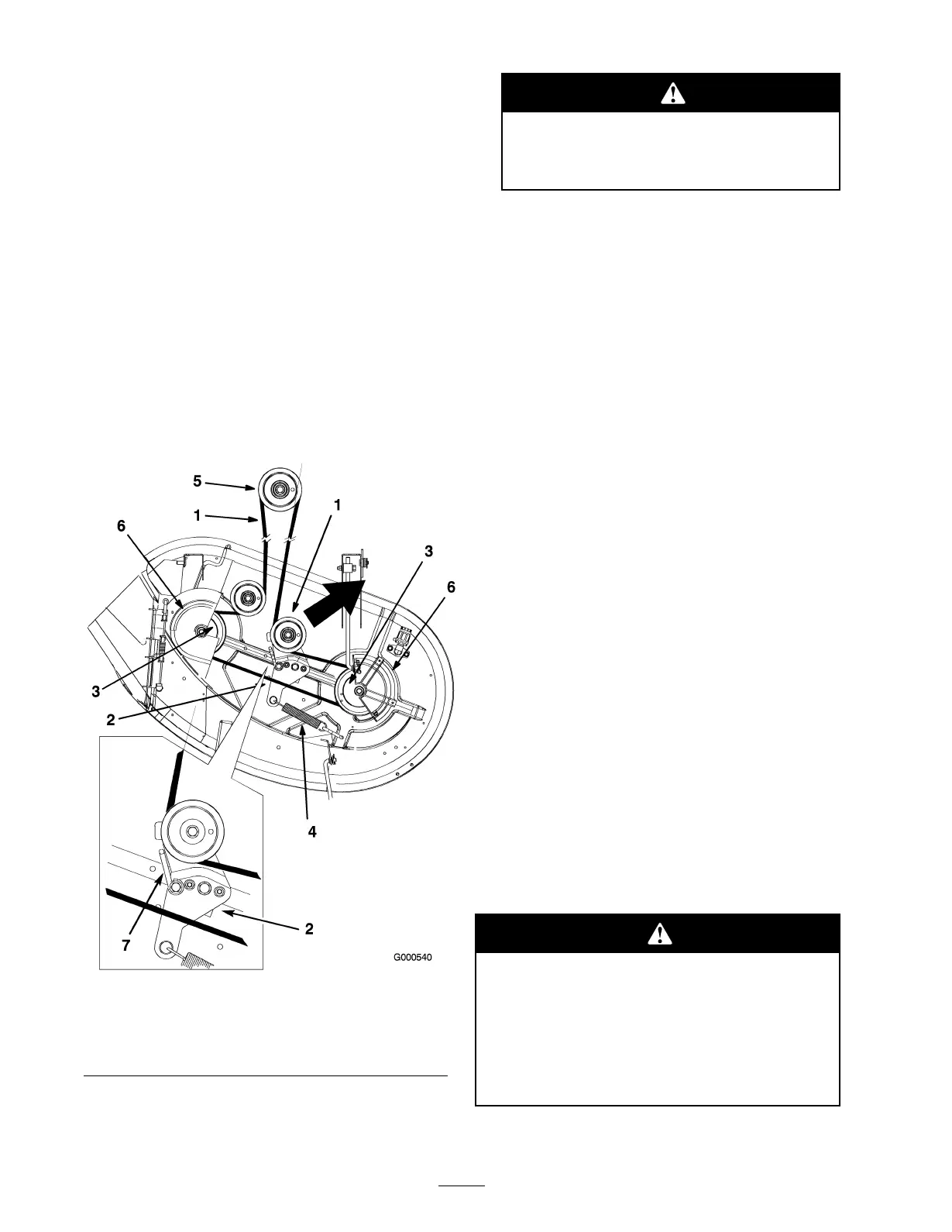
4. R emo v e the belt co v ers o v er the outside spindles
and loosen the belt guide ( Figure 51 ).
Figure 51
1. Mower belt 5. Engine pulley
2. Idler arm 6. Belt cover
3. Outside pulley 7. Belt guide
4. Spring
5. Pull the idler pulley in the direction sho wn in
Figure 51 and roll the belt off of the pulleys .
T he spring is under tension when installed
and can cause per sonal injur y .
Be car eful when r emo ving the spring .
6. R oute the new belt around the engine pulley and
mo w er pulleys ( Figure 51 ).
7. Pull the idler pulley in the direction sho wn in
Figure 51 and route the belt onto the idler pulley
( Figure 51 ).
8. R otate the belt guide , on the idler ar m, to w ards the
pulley until it stops ( Figure 51 ).
9. Tighten the belt guide ( Figure 51 ).
10. Install the belt co v ers o v er the outside spindles .
Installing the Mower
1. P ark the mac hine on a lev el surface and diseng ag e
the blade control (PTO).
2. Mo v e the motion control lev ers to the brak e
position, stop the engine , remo v e the k ey , and w ait
for all mo ving par ts to stop before lea ving the
operating position.
3. Slide the mo w er under the mac hine .
4. Lo w er the height-of-cut lev er to the lo w est
position.
5. Attac h the adjusting rod to the mac hine with the
w asher and hair pin cotter ( Figure 50 ) on eac h side
of the mo w er .
6. Slide the lev eling brac k ets onto the mounting pins
and secure them with the w ashers and hair pin
cotters ( Figure 50 ).
7. Attac h the front suppor t rods to the mac hine with
the clevis pins and hair pin cotters ( Figure 49 ).
8. Install the mo w er belt onto the engine pulley; refer
to R e placing the Mo w er Belt.
Replacing the Grass
Deector
An unco v er ed discharge opening could allo w the
la wn mo w er to thr o w objects in the operator’ s or
bystander’ s dir ection and r esult in serious injur y .
Also, contact with the blade could occur .
Nev er operate the la wn mo w er unless y ou install
a co v er plate, a mulch plate, or a g rass chute and
catcher .
1. Locate items sho wn in Figure 52 .
34