RemovingtheBlades
Thebladesmustbereplacedifasolidobjectishit,iftheblade
isoutofbalance,orifthebladeisbent.Forbestperformance
andcontinuedsafetyconformanceofthemachine,use
genuineTororeplacementblades.Replacementbladesmade
byothermanufacturersmayresultinnon-conformancewith
safetystandards.
1.Holdthebladeendusingaragorthickly-paddedglove.
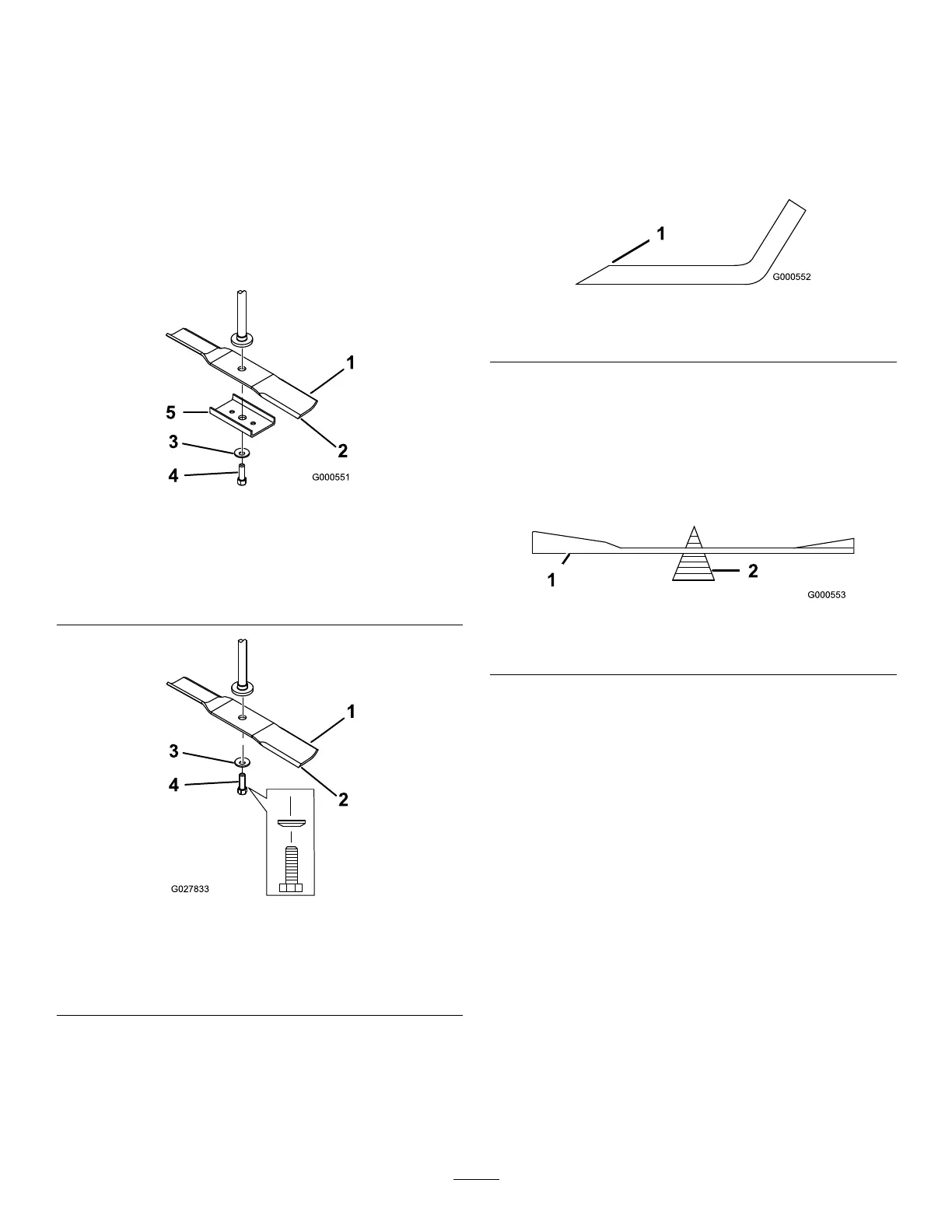
2.Removethebladestiffener(32-inchdecksonly),blade
bolt,thecurvedwasher,andthebladefromthespindle
shaft(Figure56andFigure57).
g000551
Figure56
81cm(32-Inch)Decks
1.Sailareaoftheblade
4.Bladebolt
2.Blade
5.Bladestiffener
3.Curvedwasher
g027833
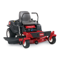
Figure57
107cm(42-Inch)Decks
1.Sailareaoftheblade3.Curvedwasher
2.Blade4.Bladebolt
SharpeningtheBlades
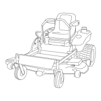
1.Usealetosharpenthecuttingedgeatbothendsof
theblade(Figure58).
Note:Maintaintheoriginalangle.
Note:Thebladeretainsitsbalanceifthesameamount
ofmaterialisremovedfrombothcuttingedges.
g000552
Figure58
1.Sharpenatoriginalangle.
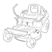
2.Checkthebalanceofthebladebyputtingitonablade
balancer(Figure59).
Note:Ifthebladestaysinahorizontalposition,the
bladeisbalancedandcanbeused.
Note:Ifthebladeisnotbalanced,lesomemetaloff
theendofthesailareaonly(Figure58).
g000553
Figure59
1.Blade2.Balancer
3.Repeatthisprocedureuntilthebladeisbalanced.
InstallingtheBlades
1.Installthebladeontothespindleshaft(Figure57).
Important:Thecurvedpartoftheblademustbe
pointingupwardtowardtheinsideofthemowerto
ensurepropercutting.
2.Installthebladestiffener(32-inchdecksonly),curved
washer(cuppedsidetowardtheblade),andbladebolt
(Figure57).
3.Torquethebladeboltto47to88N∙m(35to65ft-lb).
40