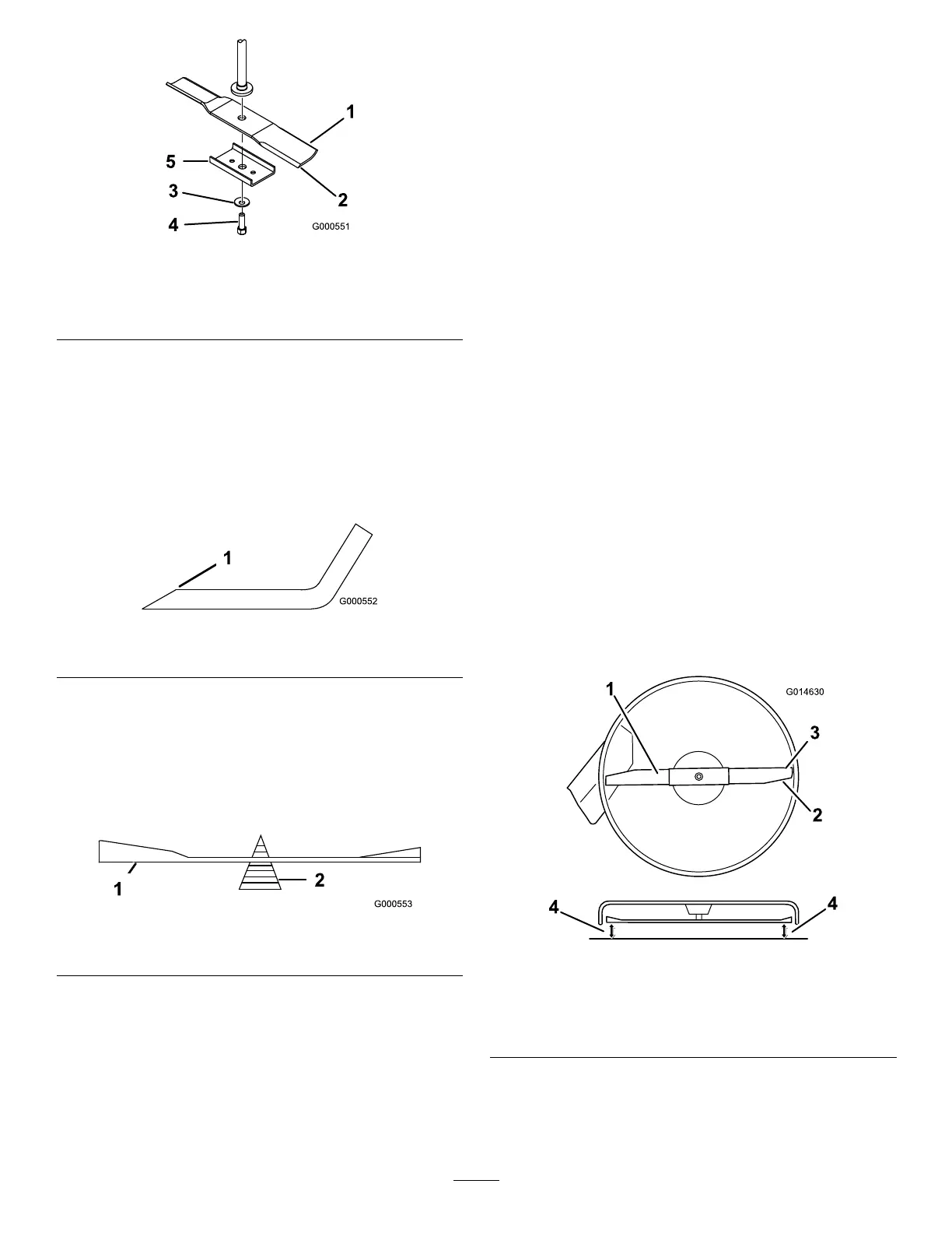
Figure49
1.Sailareaoftheblade
4.Bladebolt
2.Blade
5.Bladestiffener
3.Curvedwasher
SharpeningtheBlades
1.Usealetosharpenthecuttingedgeatbothendsof
theblade(Figure50).
Note:Maintaintheoriginalangle.
Note:Thebladeretainsitsbalanceifthesameamount
ofmaterialisremovedfrombothcuttingedges.
Figure50
1.Sharpenatoriginalangle
2.Checkthebalanceofthebladebyputtingitonablade
balancer(Figure51).
Note:Ifthebladestaysinahorizontalposition,the
bladeisbalanced,andcanbeused.
Note:Ifthebladeisnotbalanced,lesomemetaloff
theendofthesailareaonly(Figure50).
Figure51
1.Blade2.Balancer
3.Repeatthisprocedureuntilthebladeisbalanced.
InstallingtheBlades
1.Installthebladeontothespindleshaft(Figure49).
Important:Thecurvedpartoftheblademustbe
pointingupwardtowardtheinsideofthemowerto
ensurepropercutting.
2.Installthebladestiffener,thecurvedwasher(cupped
sidetowardtheblade),andthebladebolt(Figure49).
3.Torquethebladeboltto47to88N-m(35to65ft-lb).
LevelingtheMowerDeck
Checktoensurethatthemowerdeckislevelanytimeyou
installthemowerorwhenyouseeanunevencutonyour
lawn.
Themowerdeckmustbecheckedforbentbladespriorto
leveling;anybentbladesmustberemovedandreplaced;refer
toCheckingforBentBlades(page35)beforecontinuing.
Themowerdeckmustbeleveledside-to-siderstthenthe
fronttorearslopecanbeadjusted.
Requirements:
•Themachinemustbeonalevelsurface.
•Alltiresmustbeproperlyinated;refertoCheckingthe
TirePressure(page33).
LevelingfromSidetoSide
1.Parkthemachineonalevelsurfaceanddisengagethe
blade-controlswitch.
2.Settheparkingbrake,stoptheengine,removethekey,
andwaitforallmovingpartstostopbeforeleavingthe
operatingposition.
3.Settheheight-of-cutlevertomiddleposition.
4.Carefullyrotatetheblade(s)sothattheyareallsideto
side(Figure52.
Figure52
1.Bladesidetoside
3.Outsidecuttingedges
2.Sailareaoftheblade4.Measurefromthetipofthe
bladetotheatsurface
here
5.Measurebetweentheoutsidecuttingedgesandthe
atsurface(Figure52.Ifbothmeasurementsarenot
within5mm(3/16inch),anadjustmentisrequired;
continuewiththisprocedure.
37
 Loading...