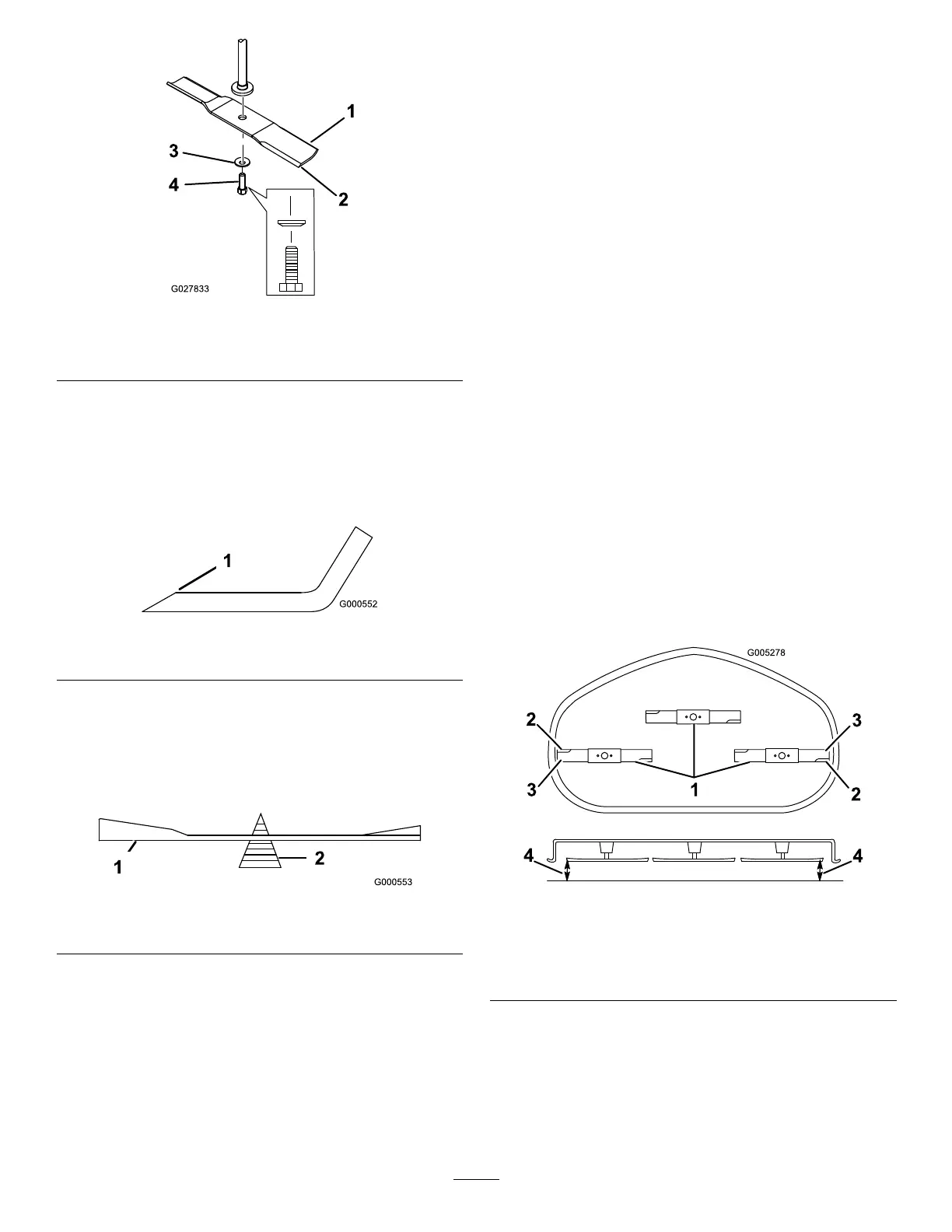
Figure48
1.Sailareaofblade3.Curvedwasher
2.Blade4.Bladebolt
SharpeningtheBlades
1.Usealetosharpenthecuttingedgeatbothendsof
theblade(Figure49).Maintaintheoriginalangle.The
bladeretainsitsbalanceifthesameamountofmaterial
isremovedfrombothcuttingedges.
Figure49
1.Sharpenatoriginalangle
2.Checkthebalanceofthebladebyputtingitonablade
balancer(Figure50).Ifthebladestaysinahorizontal
position,thebladeisbalancedandcanbeused.Ifthe
bladeisnotbalanced,lesomemetalofftheendof
thesailareaonly(Figure49).Repeatthisprocedure
untilthebladeisbalanced.
Figure50
1.Blade2.Balancer
InstallingtheBlades
1.Installthebladeontothespindleshaft(Figure48).
Important:Thecurvedpartoftheblademustbe
pointingupwardtowardtheinsideofthemowerto
ensurepropercutting.
2.Installthecurvedwasher(cuppedsidetowardthe
blade)andthebladebolt(Figure48).
3.Torquethebladeboltto47-88N-m(35-65ft-lb).
LevelingtheMowerDeck
Checktoensurethemowerdeckislevelanytimeyouinstall
themowerorwhenyouseeanunevencutonyourlawn.
Themowerdeckmustbecheckedforbentbladespriorto
leveling;anybentbladesmustberemovedandreplaced.Refer
totheCheckingforBentBladesprocedurebeforecontinuing.
Themowerdeckmustbeleveledside-to-siderstthenthe
fronttorearslopecanbeadjusted.
Requirements:
•Themachinemustbeonalevelsurface.
•Allfourtiremustbeproperlyinated.RefertoChecking
theTirePressure(page36).
LevelingfromSide-to-Side
1.Parkthemachineonalevelsurfaceanddisengagethe
bladecontrolswitch.
2.Movethemotioncontrolleversoutwardtothepark
position,stoptheengine,removethekey,andwaitfor
allmovingpartstostopbeforeleavingtheoperating
position.
3.Settheheight-of-cutlevertomiddleposition.
4.Carefullyrotatethebladessothattheyareallsideto
side(Figure51).
Figure51
1.Bladessidetoside
3.Outsidecuttingedges
2.Sailareaofblade4.Measurefromthetipofthe
bladetotheatsurface
here
5.Measurebetweentheoutsidecuttingedgesandthe
atsurface(Figure51).Ifbothmeasurementsarenot
within3/16inch(5mm),anadjustmentisrequired;
continuewiththisprocedure.
6.Movetotheleftsideofthemachine.
7.Loosenthesidelockingnut.
39