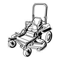
g008965
Figure90
1.Deck-liftpedal
3.Transportlock
2.Height-of-cutpin
6.Inserttheheight-adjustmentpinintothe7.6cm
(3inches)cutting-heightlocation.
7.Releasethetransportlockandallowthedeckto
lowertothecuttingheight.
8.Raisethedischargechute.
9.Onbothsidesofthedeck,measurefromthe
levelsurfacetothefronttipoftheblade(Postion
A)asshowninFigure91.
Note:Themeasurementshouldread7.6mm
(3inches)
g009196
Figure91
1.7.6cm(3inch)atposition
Aiscorrect
3.Measureherefromthe
bladetiptothehard
surface
2.8.3cm(3-1/4inch)at
positionBiscorrect
4.MeasureatpositionAand
Bonbothsides
10.Fine-tunetheadjustmentnutonthefrontdeck
liftassemblybyturningit(Figure92).
Note:T oincreasetheheight,turnthe
adjustmentnutclockwise;todecrease,turnit
counterclockwise.
Note:Ifthefrontdecklinksdonothaveenough
adjustmenttoachieveaccuratecutheight,you
canusethesingle-pointadjustmenttogain
moreadjustment.
g027344
Figure92
1.Adjustmentnut3.Reardeckadjustment
2.Jamnut4.Frontdeckadjustment
11.Toadjustthesingle-pointsystem,loosenthe
2boltsatthebottomoftheheight-of-cutplate
(Figure93).
64