Assembly
10
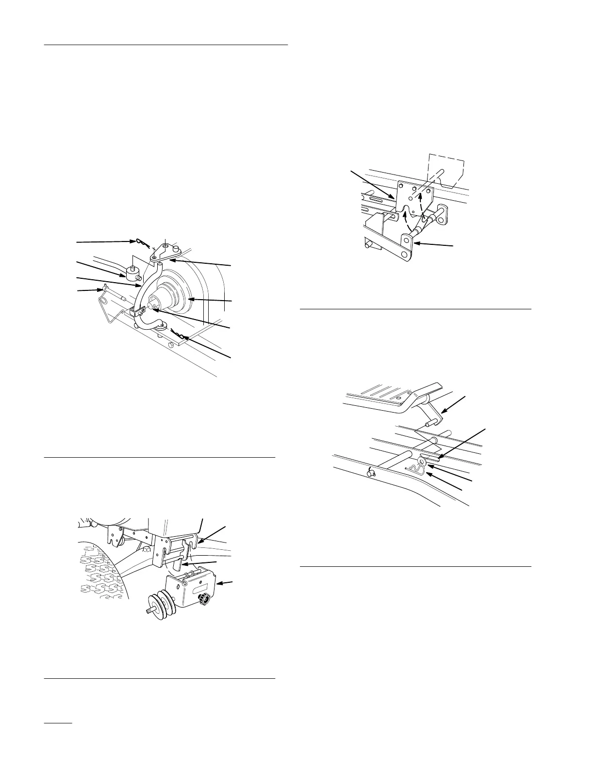
4. Remove hairpin cotters from trunnion and
bottom of yoke (Fig. 15).
5. Unlatch and remove locking clevis pin that
secures yoke assembly to clutch shaft. Pivot
yoke out and forward to remove from clutch
shaft and engagement plate (Fig. 15).
6. Remove belt from pulley (Fig. 15).
7. Assemble yoke and engagement plate and attach
locking clevis pin, trunnion and hairpin cotters
to secure (Fig. 15).
m–2691
1
2
3
4
1
7
6
5
Figure 15
1. Hairpin
cotter
2. Trunnion
3.
Engagement plate
4.
Locking clevis pin
5. Yoke
6.
Clutch shaft
7.
Inside groove
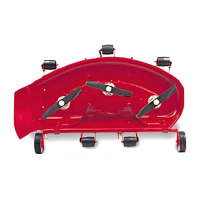
8. Open front hitch and remove pulley assembly
(Fig. 16).
2
1
m–2810
3
Figure 16
1. Pulley
assembly
2.
Front hitch
3. Latch
9. Raise attachment lift lever to the mounting
position; refer to tractor Operator’
s Manual.
10. Open mid-mount hitch lock handle. Lower
mower with attachment lift and remove front
mounting shaft (Fig. 5).
2
1
m–2825
Figure 17
1. Mid-mount
hitch
2.
Front mounting shaft
11. Remove hairpin cotter and washer from
attachment lift pin from slot in center lever bar
(Fig. 4).
1
4
2
3
m–2824
Figure 18
1. Attachment
lift
2.
Slot-center level bar
3. Washer
4.
Hair pin cotter
12. Turn the front wheels fully to the left and raise
attachment lift lever all the way to the latched
position; refer to tractor Operator’
s Manual.
Slide the mower out from under the chassis to
the the right side.
Note: Save all hardware, washers and hairpin
cotters for use when installing deck.