Assembly
6
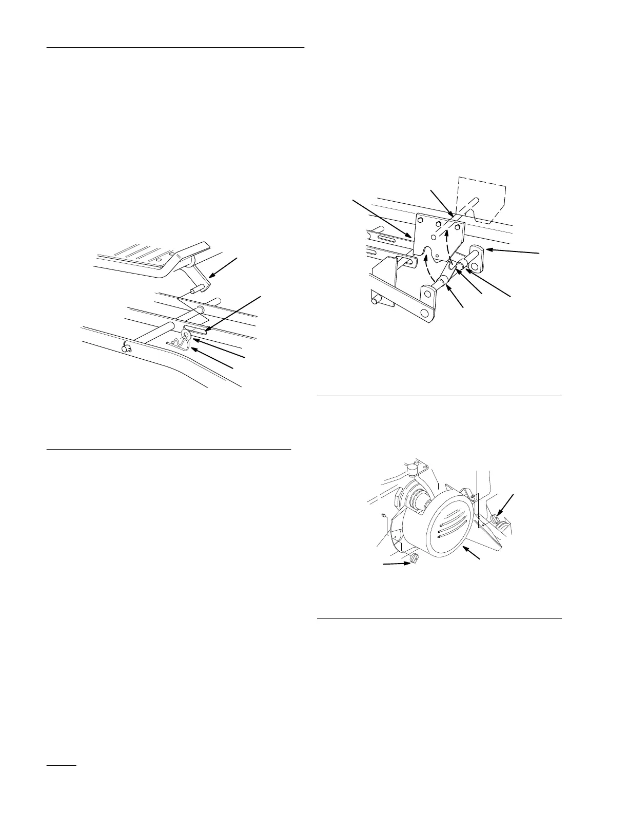
4. Slide the mower under the chassis from the right
side and align attachment lift with slot in center
lever bar (Fig. 4).
5. Straighten the front wheels, turn Dial-A-Height
knob counterclockwise, all the way, and lower
the attachment lift lever to the mounting
position; refer to tractor Operator’
s Manual.
6. Place attachment lift pin into slot in center lever
bar and secure with 3/4” (19 mm) washer and
hairpin cotter (Fig. 4).
1
4
2
3
m–2824
Figure 4
1. Attachment
lift
2.
Slot-center level bar
3. Washer
4.
Hair pin cotter
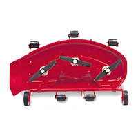
7. Rotate front mounting shaft so fork faces up and
align so spacers are between mid-mount hitch
plates (Fig. 5).
8. Lift mower with attachment lift and guide fork
to capture hitch rod (Fig. 5). Close mid-mount
hitch lock handle.
1
4
2
3
m–2825
3
5
Figure 5
1. Front
mounting shaft
2. Fork
3. Spacer
4.
Mid-mount hitch plate
5.
Hitch rod
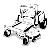
9. Remove the two wing nuts and belt cover from
the tractor (Fig. 6).
m–25341
2
2
Figure 6
6. Belt
cover
7.
Wing nut