14
1. For maximum tilling depth and transport lift height
locate link of lift chain in the lowest notch of lift lever
(Fig. 22). This position will have the greatest lift effort.
2. For minimum tilling depth and reduced lift height,
locate the link of lift chain in the upper clevis notch of
lift lever (Fig. 22). This position will have lowest lift
effort.
3. For variations of less than the three notches in the lift
lever, disconnect the lift cable from the lift arm and
rotate the trunnion (Fig. 22) Turning clockwise
increases lift height and reduces tilling depth and
counter clockwise reduces lift height and increases
tilling depth.
3
4
2
1
2309
Figure 22
1. Lowest notch
2. Highest notch
3. Lift cable
4. Trunnion
Removing the Tiller
Note: Save all hardware, washers and hairpin cotters for
re-use when installing tiller.
1. Park the machine on a level surface, disengage the
power take off (PTO), set the parking brake, and turn
the ignition key to off. Remove the key.
2. Turn the Dial-a-Height knob counterclockwise, all the
way and lower the attachment lift lever to the mounting
position; refer to Lowering Attachment.
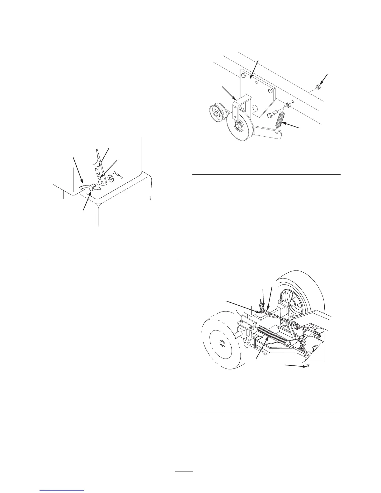
3. Remove the belt guard (Fig. 30).
4. Pull on idler arm spring to relieve belt tension and
remove tiller drive belt from tiller pulley and slide belt
out of groove (Fig. 23).
5. Remove belt from the clutch pulley. Refer to Replacing
the Power Take Off (PTO) Belt on page 16.
6. Open mid-mount hitch and remove idler bracket
assembly (Fig. 23). Unhook spring from idler arm
(Fig. 23).
7. Remove second lock nut from spring mounting bolt and
remove (Fig. 23).
2311
3
2
1
4
Figure 23
1. Mid-mount hitch
2. Idler bracket assembly
3. Spring
4. Lock nut
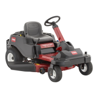
8. Raise attachment lift to the transport position and place
a block under tiller gear case.
9. Loosen lock nut on eye bolt and unhook lift assist
spring from tractor (Fig. 24).
10. Turn the Dial-a-Height knob counterclockwise, all the
way, remove block and lower the attachment lift lever
to the mounting position; refer to Lowering Attachment.
11. Remove hairpin cotter and trunnion from lift arm and
unhook long link of lift chain from lift arm (Fig. 24).
Install trunnion and hairpin cotter (Fig. 24).
2297
3
4
2
1
5
Figure 24
1. Lock nut
2. Lift assist spring
3. Hairpin cotter
4. Trunnion
5. Long link
12. Remove hairpin cotters and clevis pins from latch levers
(Fig. 25). Open latch levers and remove mounting rod.