7
Installing the Tiller Hitch and
Pulleys
1. Tip tiller onto back and support in an upright position.
Remove the 3/8 x 5-1/2 inch bolt and the
3/8 x 4-1/2 inch bolt from the tiller gear case (Fig. 2).
Discard extra nuts used as spacers for shipping.
2. Fasten hitch and spring bracket to gear case with the
bolt (3/8 x 5–1/2 inch) and nut (3/8 inch) shown in
Figure 2.
Note: Make sure the 3/8 x 4–1/2 inch bolt is install as
shown in Figure 2.
3. Install the bolt (3/8 x 4–1/2 inch) through the hitch and
gear case shown in Figure 2. Do not install the nut
(3/8 inch) at this tme.
4. Install the drive pulley, so the hub is a 1/4 inch from the
end of the drive shaft (Fig. 2). Secure pulley with a
square key and 2 square head set screws (5/16 inch).
Important Key must be located under a set screw to be
retained.
5. Align the belt cover with the hitch. Install the belt cover
onto the 3/8 x 4–1/2 inch bolt and fasten the bolt with a
nut (3/8 inch).
6. Assemble idler pulley and belt guide into lower hole of
belt guard and install onto hitch through upper hole
with a bolt (3/8 x 1–5/8 inch) and a lock nut (3/8 inch)
(Fig. 2).
1
4
13
5
7
2
10
811
9
4
3
12
m–6313
6
14
Figure 2
1. Hitch
2. Spring bracket
3. Bolt, 3/8 x 5–1/2 inch
4. Nut, 3/8 inch
5. Drive pulley
6. Key
7. Set screw, 5/16 inch
8. Idler pulley
9. Belt cover
10. Bolt, 3/8 x 1–5/8 inch
11. Lock nut, 3/8 inch
12. Tiller gear case
13. Bolt, 3/8 x 4–1/2 inch
14. Upper hole
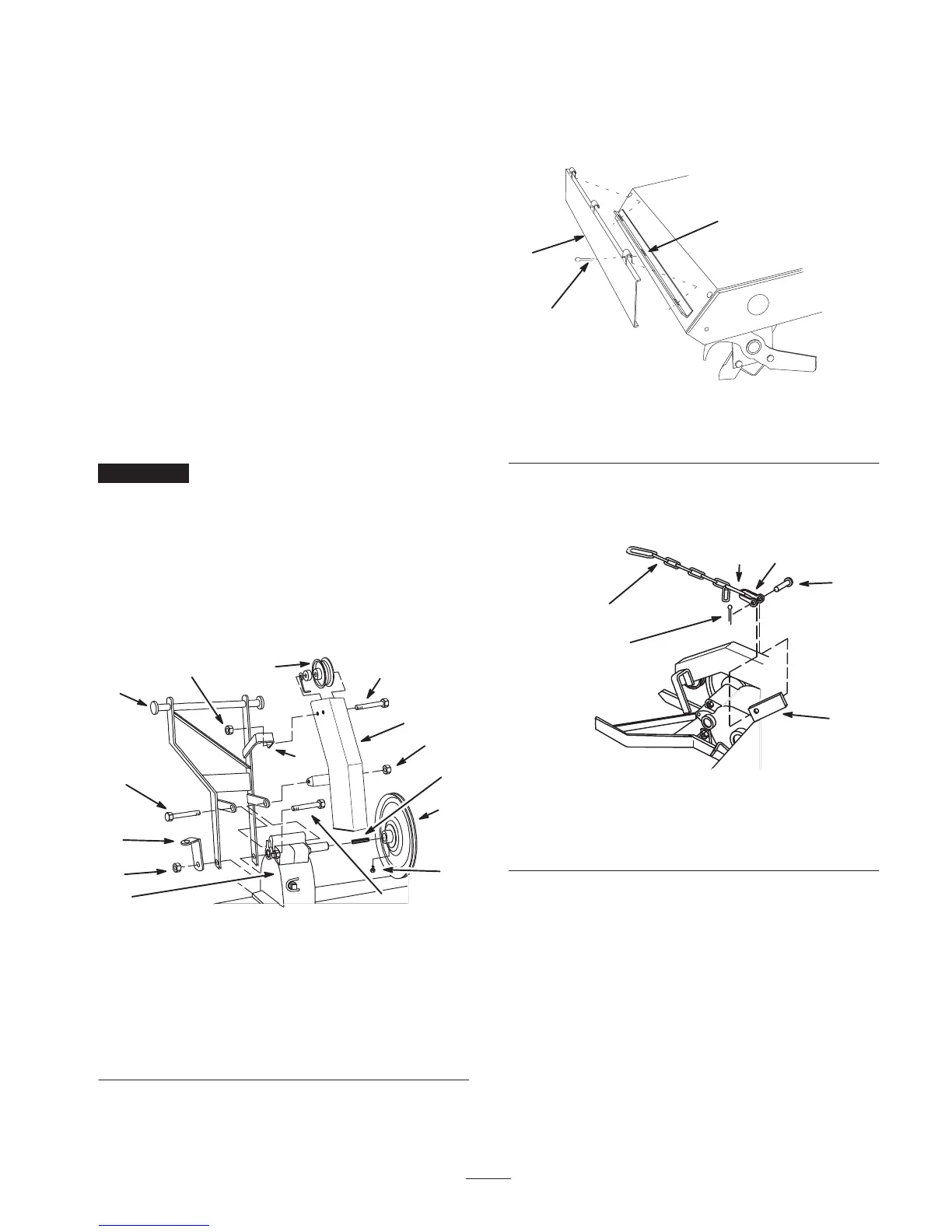
Installing the Rear Shield
1. Rotate tiller down and hook rear shield into slots at rear
of tine shield. Secure with 3 cotter pins (1 inch) (Fig. 3).
1
3
1282
2
Figure 3
1. Rear shield
2. Cotter pin, 1 inch
3. Slot
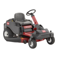
2. Attach lift chain, short link end and one link short, to
lift bracket. Secure lift chain with clevis, clevis pin and
a cotter pin (3/4 inch) (Fig. 4).
2294
1
2
3
4
6
5
Figure 4
1. Short link end
2. Clevis
3. Clevis pin
4. Bracket
5. Cotter pin, 3/4 inch
6. Lift chain
Installing the Lift Cable and Lift
Lever
1. Remove the carriage bolts at fender mount under the
seat and attaching footrests (Fig. 5).
Note: Save all hardware for use when installing fenders.
2. Unplug seat wiring harness connector and remove wire
harness from wire clip.
Note: If tractor has a 25 amp fuse clipped inside console,
remove the fuse.