8
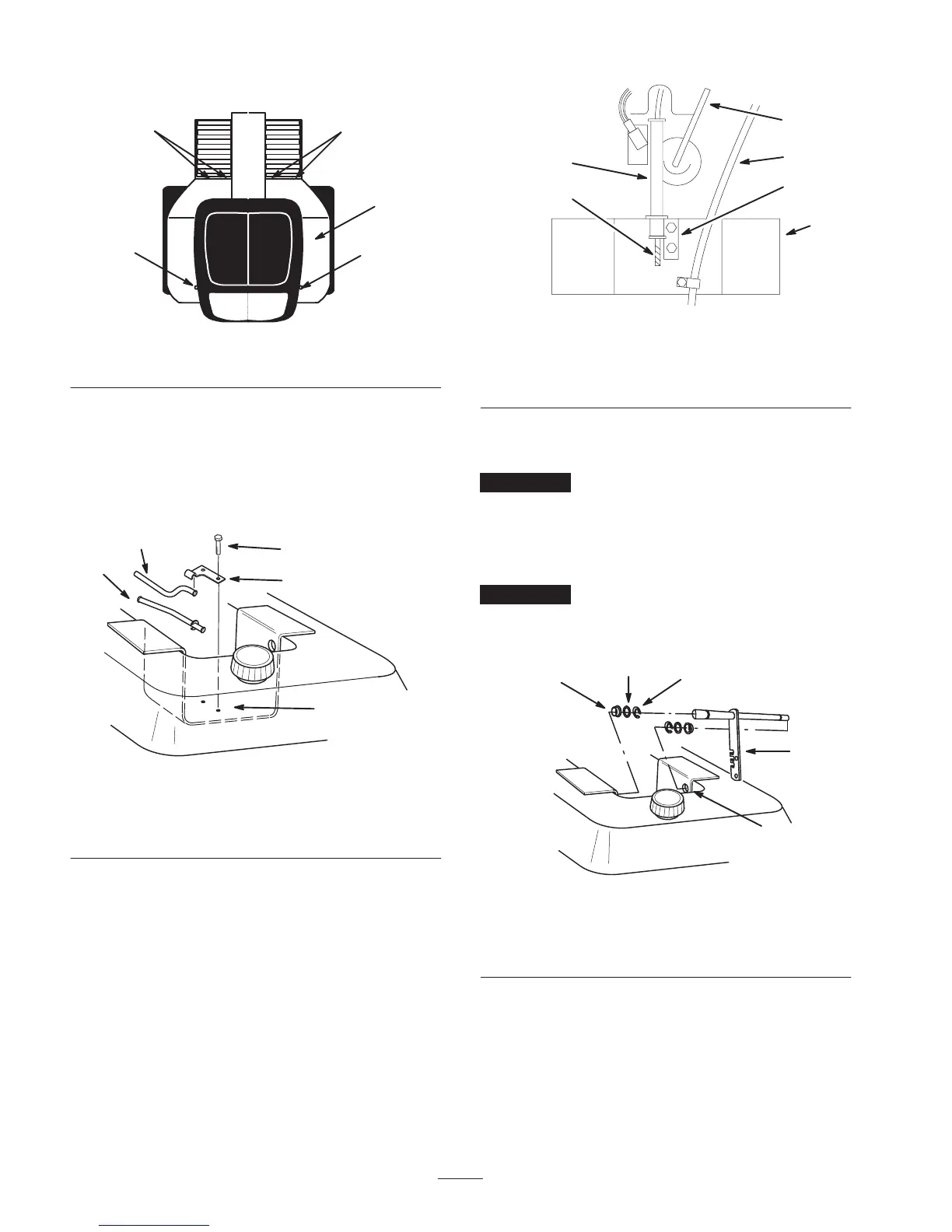
3. Remove the fender\seat pan from the tractor.
1229a
1
2
2
2
2
Figure 5
1. Fender\seat pan 2. Carriage bolt
4. Remove bolts and lock washers securing fuel tank
bracket to the top of transmission (Fig. 6).
5. Select proper cable tube; straight for gear drive and bent
for hydrostatic drive. Secure the cable tube, fuel tank
bracket and clamp with previously removed lock
washers and bolts (Fig. 6 and 7).
2293
1
2
3
4
5
Figure 6
1. Cable tube—gear drive
2. Cable tube—hydrostatic
drive
3. Clamp
4. Bracket
5. Bolt
m–5670
1
4
5
6
2
3
Top View
Figure 7
1. Cable tube—gear drive
2. Clamp
3. Bracket
4. Gear shift
5. Fuel line
6. Cable
6. Slide a shim washer and bushing onto both ends of lift
lever rod (Fig. 8).
Important Check that bushings slide easily onto rod
ends and into frame. Remove paint if necessary.
7. Position lift lever into frame and slide bushings and
shim washers outward into frame holes. Secure in
position with E-rings (Fig. 8).
Important Lift lever must not have excessive end play
(more than 0.015 inch). Use extra shim washers (0.015 and
0.020 inch thick) to reduce end play.
1
2
2291
3
5
4
Figure 8
1. Bushing
2. Shim Washer (as
required)
3. Lift lever
4. Frame hole
5. E-ring
Note: If the tractor has a 25 amp fuse clipped inside
console, install the fuse.
8. Slide ball end of attachment lift cable through cable
tube from the rear of machine.