16
Greasing and Lubrication
Service Interval/Specification
Check the gear lube level in the gear case after every 25
operating hours or once a year, whichever occurs first. Gear
lube changes are not required.
Gear lube type: SAE 90-140 API service GL-4 or GL-5.
Refill capacity: 32 oz. (946 ml)
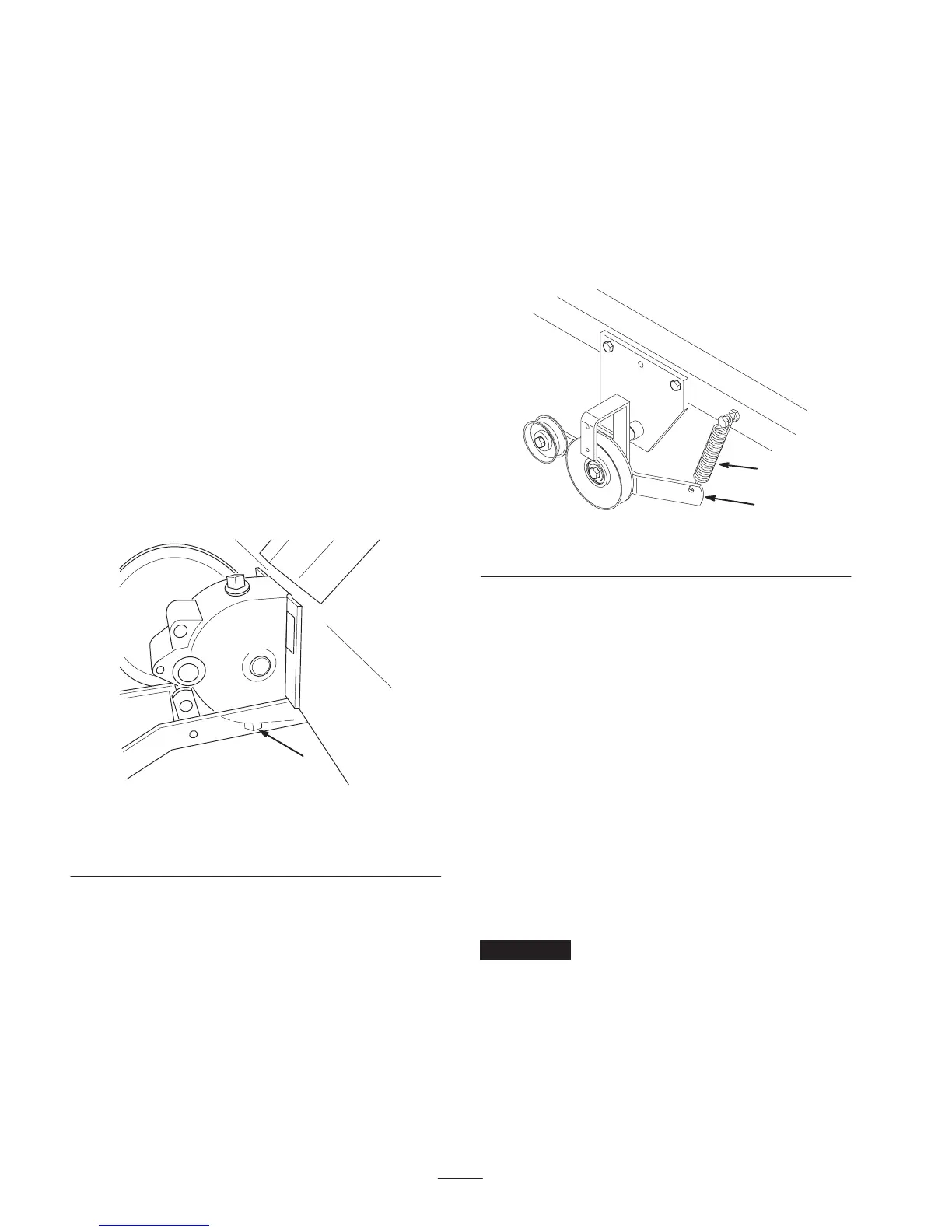
Checking Gear Lube
1. Position the tractor and tiller on a level surface and
lower the attachment lift so that the tiller tines are on
the ground. Set the parking brake and turn the ignition
key to off. Remove the key.
2. Clean the area around the lower pipe plug (Fig. 26).
3. Remove the pipe plug carefully because the oil level
may be above the level of the pipe plug.
4. If gear lube runs from the case when the plug is
removed, the lube in the case is sufficient. Oil may be
added as necessary.
m–3497
1
Figure 26
Left side of tiller shown in operating position
1. Pipe plug (hidden)
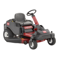
Adjusting Drive Belt Tension
The drive belt is spring loaded and needs only periodic
adjustment, to maintain proper spring tension.
Checking Drive Belt Tension
1. Disengage the power take off (PTO), set the parking
brake, and turn the ignition key to off. Remove the key.
2. As the drive belt wears, and the tiller is raised and
lowered, the spring loaded idler arm moves (Fig. 27).
3. Lower the tiller and observe the spring loaded idler arm
movement as you push on the belt. The idler arm spring
must be under tension. If it is not under tension, replace
the drive belt.
1
2
2319
Figure 27
1. Spring loaded idler arm 2. Spring
Replacing the Power Take Off
(PTO) Belt
Replacing the PTO Belt on 2001 and
Newer Models
The following instructions are for 2001 and newer models
only.
1. Unplug the clutch connector (Fig. 28).
2. Pull the PTO stop out of the clutch (Fig. 28).
3. Rotate the clutch to allow space between the belt guide
and the clutch. This will allow the belt to be installed
onto the pulley (Fig. 28).
4. Replace the belt and install new belt into the inside
pulley (Fig. 28).
Important Install belt in the inside pulley groove for
the mower.
5. Install the PTO stop back into the clutch (Fig. 28).