17
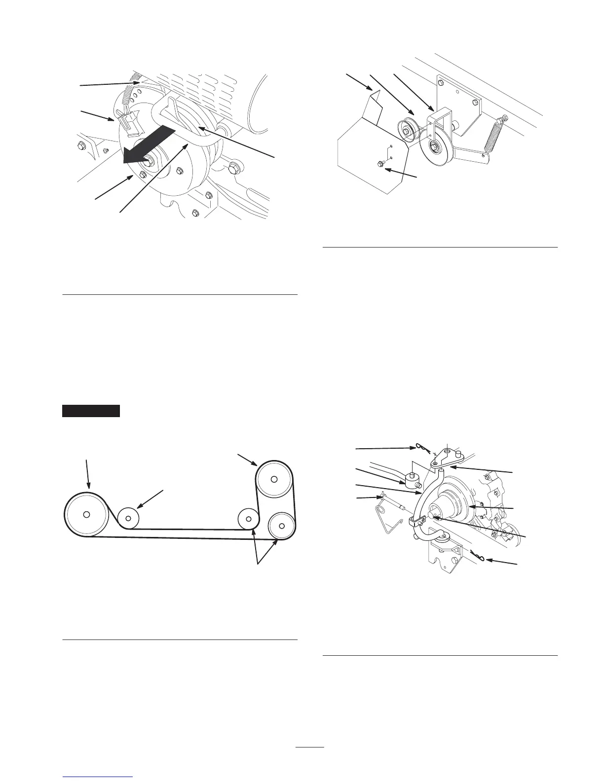
6. Install the clutch connector (Fig. 28).
m–5539
1
5
2
4
3
Figure 28
1. PTO clutch
2. PTO stop
3. Inside belt groove
4. Belt guide
5. Clutch connector
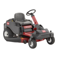
7. Route belt around and mid-mount idler pulleys, below
frame and behind right rear tire (Fig. 29).
8. Pull on idler arm spring to relieve tension and route belt
around tiller drive pulley, under tiller idler and inside
belt guide (Fig. 29).
9. Check that belt is properly routed around all pulleys and
belt guide (Fig. 29).
Important Belt must be properly routed behind belt
guide to prevent jumping off and premature failure
(Fig 30).
2313
2
4
3 1
Figure 29
1. Inner groove of (PTO)
power take off, clutch
2. Mid-mount idler pulleys
3. Tiller pulley
4. Tiller idler
10. Install belt guard to mid-mount bracket with 2 self
tapping bolts (1/4 x 1/2 inch) (Fig. 30).
2312
1
3
2
4
Figure 30
1. Belt guard
2. Idler bracket
3. Bolt, 1/4 x 1/2 inch
4. Belt guide
Replacing the PTO Belt on 2000 and
Older Models
The following instructions are for 2000 and Older Models
only.
1. Unlatch and remove locking clevis pin that secures
yoke assembly to clutch shaft. Pivot yoke out and
forward to remove from clutch shaft and engagement
plate (Fig. 31).
2. Replace belt in inside pulley groove (Fig. 31).
3. Assemble yoke and engagement plate and attach
locking clevis pin, trunnion and hairpin cotters to secure
(Fig. 31).
m–3443
1
2
3
4
1
7
6
5
Figure 31
1. Hairpin cotter
2. Trunnion
3. Engagement plate
4. Locking clevis pin
5. Yoke
6. Clutch shaft
7. Inside groove
4. Assemble yoke and engagement plate and attach clevis
pin, trunnion and hairpin cotter to secure (Fig. 31).
5. Route belt around and mid-mount idler pulleys, below
frame and behind right rear tire (Fig. 32).