Product Overview
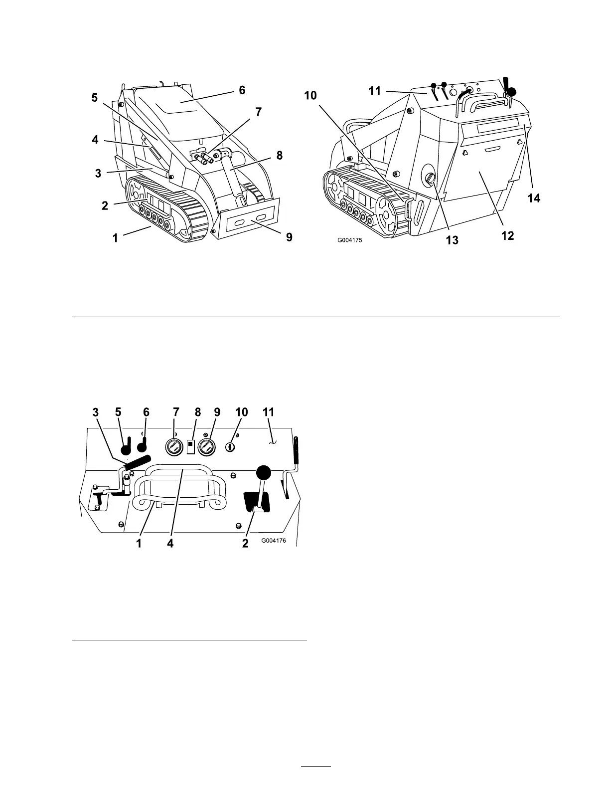
Figure 3
1. Track 5. Loader arms 9. Mount plate 13. Fuel tank
2. Track adjustment chamber 6. Hood 10. Tie-down/lift loop 14. Reverse safety plate
3. Lift cylinder 7. Auxiliary hydraulic couplers 11. Control panel
4. Cylinder lock 8. Tilt cylinder
12. Rear access cover
Controls
Become familiar with all the controls ( Figure 4 )
before y ou star t the engine and operate the traction
unit.
Figure 4
1. Traction control 7. Fuel gauge
2. Loader arm/attachment tilt
lever
8. Hydraulic oil temperature
light
3. Auxiliary hydraulics lever 9. Hour meter/tachometer
4. Reference bar 10. Key switch
5. Throttle lever 11. Parking brake lever
6. Choke lever
Key Switch
T he k ey switc h, used to star t and stop the engine ,
has three positions: off , r un, and star t.
T o star t the engine , rotate the k ey to the star t
position. R elease the k ey when engine star ts and it
will mo v e automatically to the r un position.
T o stop the engine , rotate the k ey to the off
position.
Throttle Lever
Mo v e the control forw ard to increase the engine
speed and rearw ard to decrease speed.
Choke Lever
Before star ting a cold engine , mo v e the c hok e
lev er forw ard. After the engine star ts , regulate the
c hok e to k ee p the engine r unning smoothly . As
soon as possible , mo v e the c hok e lev er all the w a y
rearw ard.
Note: A w ar m engine requires little or no
c hoking .
Reference Bar
W hen dri ving the traction unit, use the reference
bar as a handle and a lev erag e point for controlling
the traction control and the auxiliar y h y draulics
lev er . T o ensure smooth, controlled operation, do
not tak e both hands off of the reference bar while
operating the traction unit.
13