7. W hen the trac k is off of the tension wheel,
remo v e it from the dri v e sproc k et and road
wheels ( Figure 39 ).
8. Beginning at the dri v e sproc k et, coil the new
trac k around the sproc k et, ensuring that the
lugs on the trac k fit betw een the spacers on the
sproc k et ( Figure 39 ).
9. Push the trac k under and betw een the road
wheels ( Figure 39 ).
10. Star ting at the bottom of the tension wheel,
install the trac k around the wheel b y rotating
the trac k rearw ard while pushing the lugs into
the wheel.
11. T ur n the tensioning screw counter -cloc kwise
until the distance betw een the tension n ut and
the bac k of the fork tube ( Figure 37 ) is 2-3/4
inc hes (7 cm).
12. Align the closest notc h in the tension screw to
the loc king bolt hole and secure the screw with
the loc king bolt and n ut.
13. Lo w er the traction unit to the g round.
14. R e peat ste ps 2 through 13 to re place the other
trac k.
Replacing the Tracks (TX 425, Model
22307)
W hen the trac ks are badly w or n, re place them.
1. Lo w er the loader ar ms , stop the engine , and
remo v e the k ey .
2. Lift/suppor t the side of the unit to be w ork ed
on so that the trac k is 3 to 4 inc hes (7.6 to 10
cm) off of the g round.
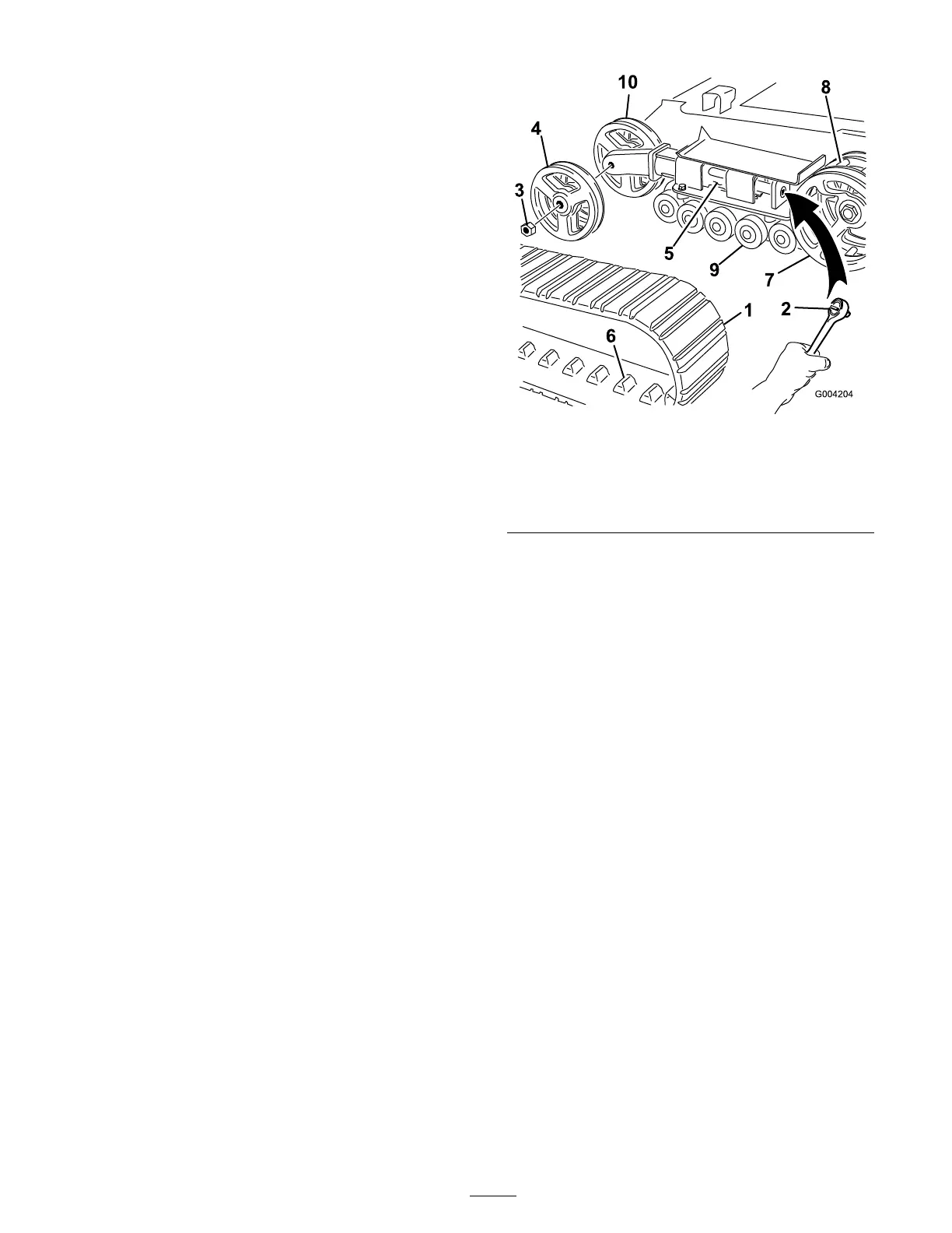
3. R emo v e the loc king bolt and n ut ( Figure 38 ).
4. Using a 1/2 inc h dri v e soc k et, release the
dri v e tension b y tur ning the tensioning screw
cloc kwise ( Figure 38 and Figure 40 ).
Figure 40
1. Track 6. Track lug
2. 1/2 inch socket 7. Drive sprocket
3. Tension wheel nut 8. Sprocket spacer
4. Outer tension wheel 9. Road wheels
5. Fork tube 10. Inner tension wheel
5. Push the tension wheel to w ard the rear of
the unit to mo v e the tension tube ag ainst the
frame ( Figure 40 ). (If it does not touc h the
frame , contin ue tur ning the tensioning screw
until it does .)
6. R emo v e the n ut securing the outer tension
wheel and remo v e the wheel ( Figure 40 ).
7. R emo v e the trac k ( Figure 40 ).
8. R emo v e the n ut securing the inner tension
wheel and remo v e the wheel ( Figure 40 ).
9. Pull the 4 larg e w ashers out of the 2 wheels , 1
on eac h side of eac h wheel.
10. Clean the old g rease and dir t out of the area
betw een where the w ashers w ere installed and
the bearings inside the wheels , then fill this
area on eac h side of eac h wheel with g rease .
11. Install the larg e w ashers on the wheels o v er
the g rease .
12. Install the inner tension wheel and secure it
with the n ut remo v ed previously ( Figure 40 ).
13. T or que the n ut to 300 ft-lb (407 N ⋅ m).
14. Install the new trac k, ensuring that the lugs in
the trac k fit betw een the spacers in the middle
of the dri v e sproc k et ( Figure 40 ).
15. Install the outer tension wheel and secure it
with the n ut remo v ed previously ( Figure 40 ).
35