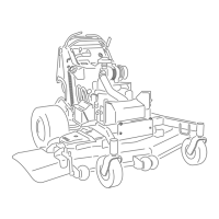
Figure59
1.Locknut
4.SpannerBushing
2.WheelBolt5.RollerBearing
3.Bushing
2.Removeonebushing,thenpullthespannerbushing
androllerbearingoutofthewheelhub(Figure59).
3.Removetheotherbushingfromthewheelhub
andcleananygreaseanddirtfromthewheelhub
(Figure59).
4.Inspecttherollerbearing,bushings,spannerbushing
andinsideofthewheelhubforwear.Replaceany
defectiveorwornparts(
Figure59).
5.Toassemble,placeonebushingintothewheelhub.
Greasetherollerbearingandspannerbushingand
slidethemintothewheelhub.Placethesecond
bushingintothewheelhub(Figure59).
6.Installthecasterwheelintothecasterforkand
securewiththewheelboltandlocknut.Tightenthe
locknutuntilthespannerbushingbottomsagainst
theinsideofthecasterforks(Figure59).
7.Greasethettingonthecasterwheel.
AdjustingtheElectricClutch
ServiceInterval:Every100hours—Checktheelectric
clutch.
Theclutchisadjustabletoensureproperengagement
andproperbraking.
1.Inserta0.015–0.021inch(0.381-0.533mm)feeler
gaugethroughoneinspectionslotinthesideofthe
assembly.Makesureitisbetweenthearmatureand
therotorfrictionsurfaces.
Thegapneedstobeatleast.015inches(0.381mm)
andnotmorethan.021inches(0.533mm).
2.Ifadjustmentisneeded,usea.015inches(0.381
mm)feelergaugetoseteachofthethreeadjustment
slotpositions.Tightenthelocknutsuntilthere
isslightbindingonthefeelergaugebutitcanbe
movedeasilywithintheairgap(Figure60).
3.Repeatthisfortheremainingslots.
4.Checkeachslotagainandmakeslightadjustments
untilthefeelergaugebetweentherotorandarmature
withveryslightcontactbetweenthem.
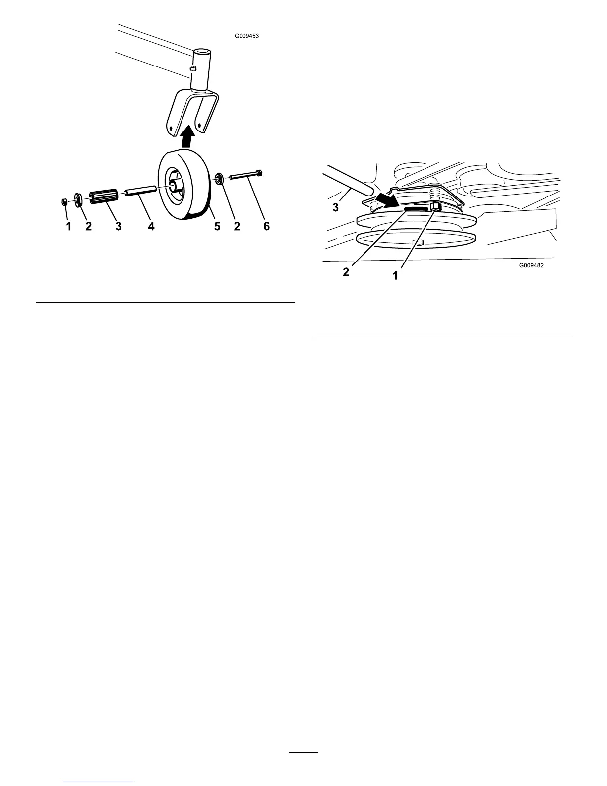
Figure60
1.Adjustingnut3.Feelergauge
2.Slot
43

 Loading...