Greensmaster Flex 1800/1820/2100/2120 Page 5 - 15 Electrical System
Traction Switch
Switch Adjustment
1. Make sure the engine is OFF and the traction lever
is in the NEUTRAL position.
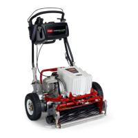
2. Remove console cover from handle to allow access
to traction switch (Fig. 12).
3. Move the traction lever forward to engage the trac-
tion drive.
4. With the traction drive engaged, there should be
from 0.030” t o 0.090” (0.8 to 2.3 mm) clearance between
theheadofthecapscrewinthetractionleverandthe
traction switch (Fig. 11).
5. If clearance is incorrect, loosen traction switch
mounting fasteners, adjust clearance and tighten fas-
teners. Recheck clearance between cap screw head
and switch after tightening fasteners. The cap screw in
the traction lever must not contact the switch.
Switch Testing
1. Make sure the engine is OFF and the traction lever
is in the NEUTRAL position. Disconnect traction switch
connector from the machine wire harness.
2. Check the continuity of the traction switch by con-
necting a multimeter (ohms setting) across the connec-
tor terminals.
3. With the traction lever in the NEUTRAL position,
there should be continuity (zero ohms) across the switch
terminals.
4. Verify that the switch opens (infinite ohms) as the
traction lever is engaged.
5. Replace switch if necessary.
Switch Removal/Installation
1. Disconnect traction switch from the machine wire
harness.
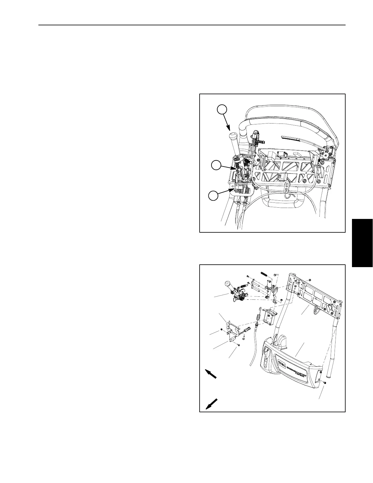
2. Remove screws and lock nuts that mount switch to
switch mount bracket on handle (Fig. 12). Remove
switch from machine.
NOTE: For proper traction switch operation, the screws
and lock nuts used to secure the interlock switch are
stainless steel. If these fasteners are replaced, make
sure to use correct fasteners.
3. Position traction switch to switch bracket and secure
with screws and lock nuts (Fig. 12).
4. Adjust traction switch as necessary (see Switch Ad-
justment above). Make sure that switch fasteners are
securely tightened after adjustment.
5. Connect switch to machine wire harness. Secure
console cover to handle.
1. Traction lever
2. Traction switch
3. Cap screw head
Figure 11
1
3
2
1. Traction switch
2. Traction lever assembly
3. Lower handle
4. Screw (2 used)
5. Lock nut (2 used)
6. Console cover
7. Screw (4 used)
8. Switch mount bracket
Figure 12
5
3
1
2
6
4
7
8
FRONT
RIGHT
Electrical
System

 Loading...