This document is a Demystification Guide for 2006 Toro LX Series Lawn Tractors and GT2000 Series Garden Tractors, specifically Form No. 492-9161. It serves as a valuable resource for service shops, providing detailed information on electrical components, troubleshooting, and circuit diagrams for these models.
The guide is structured with a table of contents that includes "Time Savers," "Glossary," and dedicated sections for specific models: LX420/LX460 and LX500/GT2100/GT2200/GT2300.
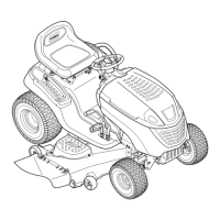
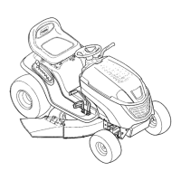
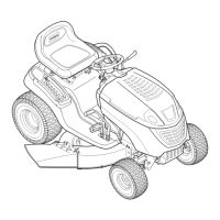
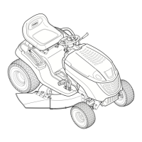
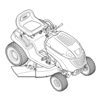
The "Time Savers" section is designed to expedite troubleshooting. It begins with instructions on "Using this manual," which explains the layout and how to navigate the information. Each product series has its own section, including an "Info List," "Wiring Diagrams," and "Circuit Diagrams." An image of the tractor helps quickly identify product sections. The "Info List" is the first page of each product section and contains a table of contents to keep things simple. Wiring diagrams are presented across two-page spreads for ease of reading, with arrows indicating connection points. Circuit diagrams are drawn individually for each circuit, showing current flow from left to right, making troubleshooting open circuits straightforward. Components with internal circuitry are enclosed with dashed lines, and those not essential for circuit function are not shown. Each component is named, and additional information is provided in parentheses. Wire colors are called out at each component, and components like switches, relays, and solenoids are drawn in the position necessary for the circuit to function.
The "Time Savers" section also includes guidance on "Using a VOM" (Volt-Ohm-Milliammeter) for checking voltage, resistance, and current. When checking voltage, it advises selecting the proper scale (e.g., 25-volt scale), using AC scales for unrectified voltage from an alternator or wall outlet, and DC scales for rectified voltages. It notes that battery voltage is always DC and that a reading of 0 will occur if measuring from ground to ground or in an open circuit. For checking resistance, it emphasizes disconnecting components from the circuit to avoid false readings, ensuring the VOM reads 0 ohms when leads are touching, and replacing the internal battery if the needle doesn't move. It also warns against using an ohmmeter to test Toro interlock modules, as battery current could damage them. When checking current, it highlights that many ammeters measure only up to 0.1 amp, while Toro riding products typically draw 3-90 amps, so a VOM capable of measuring higher currents is necessary.
Troubleshooting examples are provided, demonstrating a systematic approach. For instance, a sample problem for a GT2100 electric clutch not engaging outlines steps like testing voltage across the PTO clutch coil, moving the negative lead to chassis ground, and then to the relay plug. Another example for an LX420 not cranking illustrates using test points to divide the circuit in half. A detailed sample problem for a GT tractor that won't turn over due to a blown 20 amp fuse walks through interviewing the customer, isolating the suspect area on the wiring diagram, breaking it down into "mini-circuits" by unplugging unswitched circuits and opening switches, and then powering up mini-circuits one at a time to identify the fault (e.g., a pinched blue/white wire).
The "Glossary" section provides in-depth descriptions and testing procedures for various electrical components. Each entry includes a "Purpose" and "How It Works" section, along with detailed "Testing" steps.
Key components covered in the glossary include:
- Clutch, Electric PTO: Electrically controls the engagement and disengagement of the Power Take Off (PTO) pulley. It comprises a field (coil of wire), clutch plate, and friction plate. When 12 volts are applied to the coil, it becomes an electromagnet, drawing the friction plate to the clutch plate, causing them to rotate as one. Testing involves measuring coil resistance (should be 2.84 ohms +/- 5%) and clutch current draw (should be 3.5 amps or above). The guide also describes a "Clutch Burnishing Procedure" for new clutches to ensure smooth engagement.
- Fuse: A 20 amp fuse located at the right side of the fuel tank, wired in series between the battery positive terminal and the "B" terminal of the ignition switch. Its purpose is to protect wiring and electrical components from high current flow by creating an open circuit. Fuses are rated for specific current flow, and the guide warns against using jumper wires or additional fuses in parallel. Visual inspection and ohmmeter testing are described.
- RMC Module (Reverse Operating System): This interlock feature prevents unintentional engine-powered attachment operation in reverse. If the tractor is shifted into reverse with the PTO engaged, the electric clutch disengages or the engine stops. It can be temporarily deactivated for specific tasks by turning the key switch to the reverse caution position and pressing the reverse push button. The module is located on the back of the instrument panel with the keyswitch. Testing procedures are provided for both manual and electric PTO systems in "Normal," "Reverse Caution Unactivated," and "Reverse Caution Activated" modes. Direct testing of the RMC module is not practical; instead, inputs and outputs are tested. A circuit testing table for the Electric PTO clutch lists terminals, wire colors, connected components, and expected conditions.
- Manual PTO Clutch (RMC Module): Similar to the electric PTO clutch, this system prevents the engine from shutting down when shifting into reverse or when the operator leaves the seat with the PTO on, if the reverse caution mode is not activated. A circuit testing table for the Manual PTO clutch lists terminals, wire colors, connected components, and expected conditions.
- Relay (Electric PTO): Part of the wiring harness, located behind the fuel tank near the PTO connector. Its purpose is to disconnect the electric PTO clutch from ground when the PTO is engaged and the shift lever is in reverse, unless reverse caution mode is activated. It functions as an electrically activated single pole double throw switch. Testing involves verifying coil resistance (approximately 105 ohms) and continuity between terminals under various conditions.
- Solenoid, Starter: Located under the rear fender behind the battery. Its purpose is to connect the battery to the starter motor when the ignition switch is turned to "START," protecting the ignition switch from high current. It consists of a coil of wire and a bar-type switch. When 12 volts are applied to the coil, it becomes an electromagnet, pulling the bar to close the switch. Testing involves checking for open continuity when de-energized and closed continuity when 12 VDC is applied, and listening for a "click."
- Switch, Brake: Attached to the tractor frame, under the fuel tank, near the brake lever. As part of the safety interlock system, it has two sets of terminals: one prevents cranking if the brake is not applied, and the other causes the engine to shut down if the operator leaves the seat with the brake released. The plunger is depressed when the brake is applied, closing contacts "C" and "D" to allow voltage to the PTO switch and starter solenoid, and opening contacts "A" and "B" to prevent the magneto from grounding. Testing involves checking continuity with the plunger depressed and not depressed.
- Switch, Parking Brake (Manual PTO): Located under the fuel tank near the locking lever. Part of the safety interlock system, it shuts down the engine if the operator leaves the seat without engaging the parking brake. When latched, the plunger is depressed, closing the contacts. Testing involves checking continuity with the plunger in and out.
- Switch, Key: Provides proper switching for the starter, ignition, accessories, and safety circuits. It has four positions: STOP, REVERSE CAUTION, NORMAL MOWING, and START. The START position is spring-loaded. Testing involves verifying continuity between terminals for each switch position.
- Switch, Reverse: For units with constant velocity transmissions (CVT), it's attached to the underside of the tractor next to the reverse lever. For hydrostatic transmissions, it's on the right side of the transmission near the brake. It provides a ground signal to the RMC module when the shift lever is in reverse. Testing involves checking continuity between the switch terminal and ground with the shift lever in forward and reverse.
- Switch, Seat (Electric PTO Clutch): Shuts down the engine if the operator leaves the seat with the brake not applied, or disengages the PTO clutch if the operator leaves the seat with the PTO engaged. It has normally closed contacts that open when the operator is on the seat. One contact is in series with the magneto through the brake switch, and the other is connected to the relay through the RMC module. Testing involves checking continuity between terminals and ground with and without an operator in the seat.
- Switch, Seat (Manual PTO Clutch): Shuts down the engine if the operator leaves the seat with the PTO engaged or the brake released. It has normally closed contacts that open when the operator is on the seat. One contact is in series with the magneto through the brake switch, and the other is in series with the magneto through the PTO switch. Testing involves checking continuity between terminals and ground with and without an operator in the seat.
- Switch, PTO (Electric PTO): Used to engage the electric clutch and is part of the safety circuit. It prevents engine cranking with the PTO switch on, prevents the electric PTO clutch from re-engaging after moving the shift lever in and out of reverse without activating reverse caution mode, and prevents re-engagement if the operator gets off and back on the seat. It uses three sets of contacts: A-Com (normally closed, wired between brake switch and start solenoid), B-Com (normally open, connected between relay coil and normally open relay contact), and C-Com (normally open, connected between A1 terminal of ignition switch and electric clutch). Testing involves removing the switch and checking continuity across terminals in "OFF" and "ON" positions.
- Switch, PTO (Manual PTO): Located under the hood near the actuation rod. This double-pole plunger type switch has four terminals, one pair normally open and one pair normally closed. The plunger is depressed when the PTO lever is in the off position. Testing involves checking continuity with the plunger depressed and not depressed.
- Systems Indicator Monitor / Hourmeter: The monitor panel lights indicate the position of the brake and PTO controls and the battery charging system condition. The LCD displays accumulated engine hours and flashes when maintenance is due. It's a solid-state device powered by battery voltage from the A1 terminal of the keyswitch. Internal circuits monitor battery voltage and the status of brake and PTO switches. Direct testing is not practical; instead, inputs to the unit at the wiring harness connector are tested. This includes checking battery voltage, and continuity with the PTO off and brake applied.
The guide also includes detailed wiring and circuit diagrams for the LX420, LX460, LX500, GT2100, GT2200, and GT2300 models, covering:
- Starter Motor Circuit (ignition switch in "start")
- Spark Circuit (ignition switch in "start," "Normal" with PTO "on," "Normal" with operator "off" and brake "on" and PTO "off," "Normal" with operator "off" and brake "on" and PTO "on")
- Reverse Operating System (ignition switch in "Normal" with PTO "on" and transmission in "reverse," "Reverse Caution" with PTO "on" and transmission in "forward," "Reverse Caution" with RMC "activated" and transmission in "reverse" and PTO "on")
- PTO Circuit (ignition switch in "Normal" with operator "off" and brake "on," "Normal" with operator "off" and PTO "on," "Reverse Caution" with PTO "on" and transmission in "reverse," "Reverse Caution" with RMC "activated" and PTO "on" and transmission in "reverse")
The document emphasizes that The Toro Company reserves the right to change product specifications or the manual without notice.