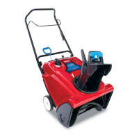
Figure36
1.Drivebeltcover6.Drivebelt
2.Bolt(3)7.Rotorshaft
3.Rotorpulleybolt
8.Brakespring(unhookfrom
idlerarmhere)
4.Curvedwasher
9.Idlerpulley
5.Rotorpulley10.Enginepulley
2.Unhookthebrakespringfromtheidlerarmto
releasethebelttension(
Figure36).
3.Removethescrewandcurvedwasherthatholdsthe
rotorpulley(Figure36).
4.Removetherotorpulleyandthedrivebelt
(
Figure36).
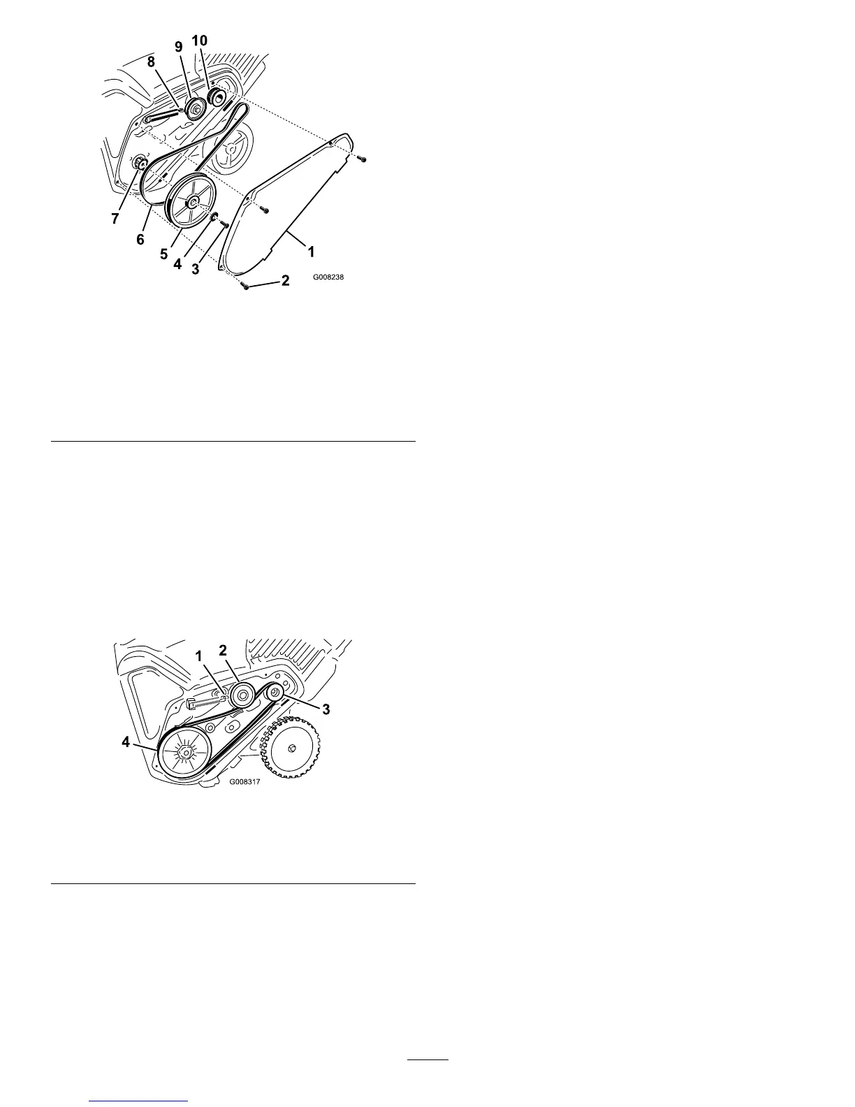
5.Installthenewdrivebelt,routingitasshownin
(Figure37).
Figure37
1.Brakespring(installon
idlerarmhere)
3.Enginepulley
2.Idlerpulley4.Rotorpulley
Note:Routethenewdrivebeltrstaroundthe
enginepulley,thentheidlerpulley,andnallyaround
thelooserotorpulleypositionedjustabovetherotor
shaft(Figure36).
6.Installtherotorpulleyontotherotorshaft
(Figure36).
7.Installthecurvedwasherandtherotorpulleybolt
andtightenthemsecurely(Figure36).
Note:Theconcavesideofthecurvedwashergoes
againsttheoutsideofthepulley.
8.Installthebrakespringontotheidlerarm(
Figure37).
9.Installthedrivebeltcoverwiththeboltsyou
removedinstep1.
Note:Ensurethatthedrivebeltisproperlyadjusted
andoperating;refertoCheckingtheControlCable
andAdjustingtheControlCable.
16
 Loading...