Figure7
1.Cableclamp(2)
Important:Ensurethatthecurvedsideofthe
cableclampisagainstthehandleandthatthe
cableisroutedbelowtheclampbolt.Thecable
mustbeinastraightlinefromthecableclamp
tothepointwhereitattachestothewheelclutch
lever.
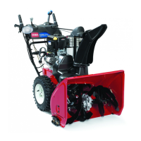
4.Pullthecablejacketdowngentlyuntilthewheel
clutchleverisdownandtheslackisoutofthecable,
thentightenthecableclampnutsecurely(Figure8).
Figure8
5.Squeezetheleverfully,thencheckthegapbetween
thebottomofthehandleandthewheelclutchlever
end(Figure9).
Figure9
Note:Thegapshouldbeapproximatelythe
thicknessofapencil(1/4inchor6mm).Ifitis
greater,loosenthecableclampnut,slidethecable
jacketupslightly,tightenthecableclampnut,and
checkthegapagain.
6.Repeatsteps2through5fortheothercable.
3.InstallingtheTraction
ControlLinkage
Procedure
1.Removethehairpincotterandwasherfromthe
lowerendofthespeedcontrolrodandinsertthe
lowerendoftherodintothelowerlinkarmsothat
thebentendofthespeedcontrolrodfacesrearward
(Figure10).
Figure10
2.Securethelowerendofthespeedcontrolrodwith
thewasherandhairpincotterthatyoupreviously
removed.
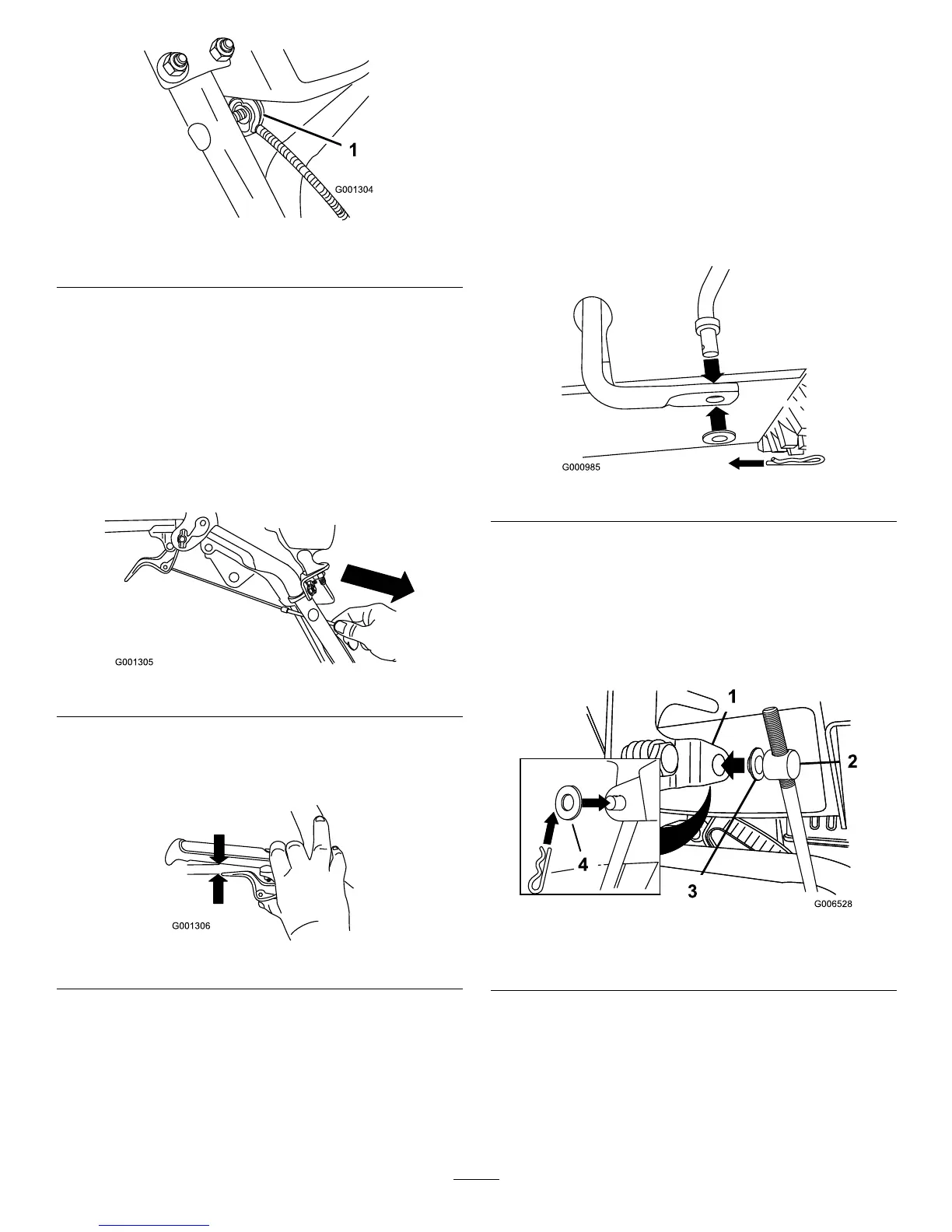
3.Removethehairpincotterandtheouterwasher
fromthetrunnionontheupperendofthespeed
controlrod(Figure11).
Figure11
1.Speedselectorlever
3.Innerwasher
2.Trunnion
4.Outerwasher
Note:Tomakeinstallationeasier,leavetheat
washeronthetrunnion(Figure11).
4.ShiftthespeedselectorleverintoPositionR2.
5.Rotatethelowerlinkarmfullyupward
(counterclockwise)(Figure12).
9
 Loading...