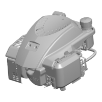
IGNITION TIMING
The' ignition timing is preset at the factory and is not
adjustable. For troubleshooting purposes,
it
is possible
to
make an approximate check of the ignition timing
using reference marks on the blower housing and a
chaff screen bolt (Figure 2). This check can be performed
by a continuity test.
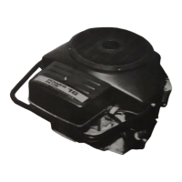
M-1675
FIGURE
2.
IGNITION
TIMING
MARKS
Continuity
Test
spark plugs.
1.
Pull spark plug wires off spark plugs and remove
Accidental starting of the engine
injury or death. Remove spark plugs before
proceeding.
can result in severe personal
2. Turn ignition on.
3. Connect a voltmeter between the negative
(-)
coil
terminal (larger diameter of the two threaded posts)
and a good engine ground.
The electronic ignition produces
current which can cause elec-
trical shock.
Do
not touch electrical components
or wires while ignition
is
on.
4. Rotate the flywheel slowly by hand in the clockwise
direction until the voltmeter reading switches from
approximately
1
volt to battery voltage. At this point,
one of the chaff screen bolts should lie between the
two timing marks on the blower housing. To recheck
timing, the flywheel must be rotated another
complete revolution
in
the clockwise direction.
Moving the flywheel back and forth across the
reference timing mark will not activate the electronic
ignition control.
5.
Install spark plugs and wires.
IGNITION COIL
To-test primary and secondary windings within the
ignition coil first make sure the ignition power is off and
coil is at room temperature of
70°F
(21
°C).
1.
Use a Simpson 260
VOM
or equivalent.
2. Place a black lead on negative
(-)
coil terminal and
red lead
to
positive
(+)
coil terminal. Primary
resistance should read between 2.90-3.60 ohms.
3. Change resistance setting on ohmmeter. Place
ohmmeter leads inside of spark plug cable holes
(Figure 3). Secondary resistance should read
between 14,500-19,800 ohms.
4.
If
either of the above resistances are not within
specification, replace coil.
OHMMETER
FIGURE
3.
COIL
TEST
8-2
 Loading...