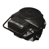
Engine
Disassembly
DISASSEMBLY/ASSEMBLY
When complete engine disassembly is necessary, first
remove all complete assemblies. Individual assemblies
such as fuel pump and carburetor can be disassembled
and repaired at another time.
Suggested Disassembly Order
1. Drain engine oil.
2. Disconnect all exhaust and electrical lines.
3. Removeengine from its mountingsand place upright
in a suitable work area.
A
2
x
4 wood frame 10 inches
per side provides a suitable fixture to hold the
engine and prevent damage
to
the crankshaft.
4. Remove
oil
fill
tube, and all housings, shrouds,
blower housings, etc.
5.
Remove flywheel.
6.
Remove ignition trigger and gear cover, being
careful
to
protect oil seal from keyway damage.
7.
Remove crank gear, using a gear puller and ring.
8.
Remove all accessories such as oil filter, starter,
9.
Remove oil pump and cylinder heads.
10. Remove valves, springs, lifters, etc.
11. Remove camshaft and gear assembly.
12. Remove oil cooler.
13. Set engine on its back to remove oil base cover, oil
14. Remove connecting rods and pistons.
intake manifold, fuel lines, spark plugs, etc.
pickup cup and oil pickup tube.
15. Remove oil base casting, crankshaft
and lower bearing.
Keep all parts in their respective orders. Keep valve
assemblies together. Return rod caps to their respective
pistons. Analyze the reasons for parts failure.
Suggested Assembly Procedure
Engine assembly is normally the reverse
of
the dis-
assembly procedure, observing proper clearances and
torques. Use a torque wrench
to
assure proper tightness.
Coat the internal engine parts with oil as they are
assembled. After the internal engine parts are assem-
bled, the engine should turn over by hand freely. Use
only genuine Onan parts and special
tools
when
reassembling your engine.
1. Use proper bearing driver to install top main bearing
2. Insert lower main bearings in oil base casting.
after coating
it
with a light film of oil.
3. Insert crankshaft, oil base casting, and crankshaft
4. Install pistons and connecting rods.
5.
Install oil pickup tube with its spring, oil pickup cup,
gear.
and oil base cover.
6.
Install oil cooler.
7.
Install camshaft and gear assembly; align crank
8.
Install valve assemblies, oil pump, oil cooler, and
9.
Install all accessories such as oil filter, starter fuel
10. Install gear cover with oil seal, trigger ring, and
11. Check valve clearance.
12. Install all housings, shrouds, intake manifold, and oil
fill tube. Always use a new oil
fill
tube seal when
reinstalling the oil fill tube.
gear mak with cam gear mark.
cylinder heads.
lines and spark plugs.
flywheel..
13. Fill engine oil.
Operation
Start engine and check oil pressure. Run for approx-
imately 15 minutes 'to bring engine
to
operating
temperatures. Check for oil leaks, fuel leaks, and exhaust
leaks. Adjust carburetor and governor for speed and
sensitivity.
Testing Compression
The compression tester
is
used to determine the
condition of valves, pistons,-piston rings and cylinders.
To check compression:
1. Run the engine until thoroughly warm.
2. Stop engine and remove spark plugs.
3. Remove air cleaner and place throttle and choke
in
4.
Insert the compression gauge in one spark plug
5.
Crank the engine and note the reading.
the wide open position.
hole.
Refer
to
SPECIFICATIONS
for compression pressures.
There may be variations due to equipment, temperature,
atmospheric conditions and altitude. These pressures
are for a warm engine at cranking speed (about 300
rpm).

 Loading...