Ignition and Battery Charging
IGNITION SYSTEM DESCRIPTION
This engine is equipped 'with 'an electronic battery
ignition system. Both spark plugs fire, simultaneously,
thus the need for a distributor is eliminated. The
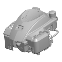
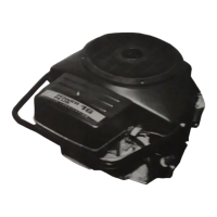
electronic ignition module is located on the engine gear
cover below the flywheel. The module receives a timing
signal from magnets within the trigger ring which rotates
with the engine crankshaft (Figure
1).
If
the electronic.
ignition is suspected of malfunctioning, proceed as
follows:
TRIGGER
RING
IGNITION
MODULE
\
ES-1670
FIGURE
1.
IGNITION MODULE AND TRIGGER RING
1.
Check all electrical connections to be sure they are
clean and tight.
If
all connections are good and
wiring is intact, go
to
step
2.
2.
Refer
to
IGNITION COIL section to test coil for
proper resistance.
If
coil checks out good, go
to
step
3.
current which can cause elec-
The electronic ignition produces
trical shock.
Do
not touch electrical components
or wires while ignition is on.
Accidental starting of the engine
can result in severe personal
injury or death. Remove spark plugs before
proceeding.
Ignition of cylinder gases can
cause severe personal injury.
Ground spark tester away from spark plug hole.
3.
Pull spark plug wires
off
spark plugs and remove
spark plugs. Connect an approved spark tester to
each of the spark plug wires and ground them away
from spark plug hole. Turn key on and crank engine
over for
5
seconds while watching for spark.
If
a
spark occurs regularly, the problem is not in the
ignition system.
If
no spark occurs, go to step
4.
Incorrect wiring can cause elec-
tronic ignition damage.
Do
not
attach any lead or jumper with power (such as
B+)
to
coil negative terminal.
4.
Connect a jumper lead directly from the positive
battery terminal to the positive
(+)
coil terminal
(smaller diameter of the two threaded posts). Crank
engine over while watching for spark.
If
spark
occurs, the problem is in the low oil pressure cut out
switch (if equipped) or related wiring, the lubricating
system (low oil pressure), or in the other circuitry
bringing voltage to the coil.
If
no spark occurs, go to
,.step
5.
5.
Connect positive side of voltmeter to negative
(-)
coil terminal (larger diameter of the two threaded
posts) and negative side of voltmeter to engine
ground. Turn key on and rotate flywheel slowly by
hand while observing voltmeter. Voltage should
switch between battery voltage and
1-1.5
for each
revolution.
If
voltage does not switch properly,
replace ignition module.
tronic ignition damage.
Do
not
Incorrect wiring can cause elec-
attach any lead
or jumper with power (such as
B+)
.to coil negative
terminal.
6.
Install spark plugs and wires.
If
ignition module is
being replaced, be sure
to
connect red lead from
new ignition module to positive
(+)
terminal of coil,
black lead from module
to
negative
(-)
terminal of
coil.
 Loading...