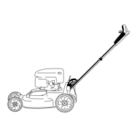
Figure15
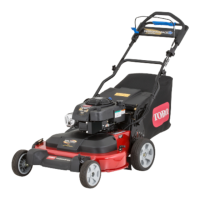
1.Theoillevelistoolow;
addoiltothecrankcase.
3.Theoilleveliscorrect.
2.Theoillevelistoohigh;
removeoilfromthe
crankcase.
•Iftheoillevelistoolow,addasmallamountofoil
slowlytotheoil-lltube,andthenrepeatsteps
3through5untiltheoilleveliscorrectasshown
inFigure7.
•Iftheoillevelistoohigh,draintheexcessoiluntil
youobtainthecorrectoillevelonthedipstick;to
draintheexcessoil,refertoChangingtheEngine
Oil(page18).
Important:Iftheoillevelinthecrankcaseis
toolowortoohighandyouruntheengine,
youmaydamagetheengine.
6.Installthedipsticksecurelybyhand.
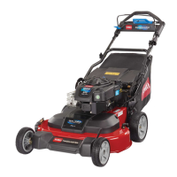
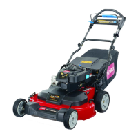
AdjustingtheCuttingHeight
WARNING
Adjustingthecuttingheightmaybringyouinto
contactwiththemovingblades,causingserious
injury.
•Stoptheengineandwaitforallmovingparts
tostop.
•Donotputyourngersunderthehousingwhen
adjustingthecuttingheight.
Adjustthecuttingheightasdesired;refertoFigure16and
Figure17.
Note:Toraisethemachine,movethefrontandrearcutting
heightleversforward;tolowerthemachine,movethecutting
heightleversrearward.Setthefrontandrearwheelstothe
sameheightunlessspecialcircumstancesrequireotherwise;
refertoOperatingTips(page16).