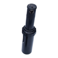
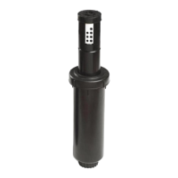
FLEX800
TM
Series Sprinklers
FLX55-6 – 24-Position TruJectory
TM
October, 2014
nozzles and a main nozzle adapter, and 10
different color-coded inner/intermediate
nozzles. The main nozzle shall incorporate a
trajectory adjustment that provides a main
nozzle discharge angle from 7 to 30 in 1
increments. Trajectory adjustment shall be
capable while the sprinkler is in operation or
not. The sprinkler shall identify the
trajectory adjustment setting from the top of
the sprinkler. Close-in watering distribution
shall be achieved by an inner nozzle capable
of adjusting the distribution profile to
optimize uniformity. The cap shall identify
the installed main nozzle and the date of
manufacture.
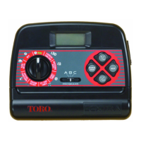
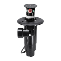
The pilot valve assembly shall incorporate
one of five electrical activation types
(described below) to control the ON-OFF
operation of the sprinkler. It shall provide
four pressure-point selections (50, 65, 80 and
100 psi; 3,5, 4,5, 5,5 and 6,9 Bar), with a
vandal-resistant locking feature that ensures
the desired setting is maintained. The
pressure points shall be graphically illustrated
in psi and kg/cm2. The pilot valve assembly
shall include a pressure-regulation feature
that continuously monitors the operating
pressure inside the sprinkler body, making
the necessary adjustments to ensure the
desired and set regulation pressure is
maintained. The pilot valve assembly shall
incorporate a manual control feature that is
accessible from the top and allows the
sprinkler to be manually selected “ON”,
“OFF” or placed in the “AUTO” position
awaiting commands from the control device.
The manual selector shall be red in color for
enhanced visibility. The pilot valve assembly
shall be stamped with the manufactured
date.
The sprinkler shall incorporate an electrical
solenoid for activation of the integrated
control valve in one of five activation types
as described below.
Standard Solenoid
The Standard solenoid shall be suitable for
24 VAC, 50/60 Hz service with an inrush
current of 0.30 A @ 50/60 Hz, and holding
current of 0.20 A @ 50/60 Hz and shall be
capable of withstanding a voltage surge of up
to 9k volts in the common and normal
modes without failure.
Spike Guard Solenoid
The Spike Guard solenoid shall be suitable
for 24 VAC, 50/60 Hz service with an
inrush current of 0.12 A @ 50/60 Hz, and
holding current of 0.10 A @ 50/60 Hz. and
shall be capable of withstanding a voltage
surge of up to 20k volts in the common and
normal modes without failure.
Nickel-Plated Spike Guard Solenoid
The Nickel-Plated Spike Guard solenoid
shall be suitable for 24 VAC, 50/60 Hz
service with inrush current of 0.12 A @
50/60 Hz, and holding current of 0.10 A @
50/60 Hz. and shall be capable of
withstanding a voltage surge of up to 20k
volts in the common and normal modes
without failure. It shall also have a nickel-
plated core to provide additional corrosion-
resistance in potable and non-potable water
applications.
DC Latching Solenoid
The DC latching solenoid shall be activated
by a momentary low-voltage pulse that
moves the plunger from the “OFF” to the
“ON” position where it is maintained by a
permanent magnet in the solenoid. To
deactivate, a second momentary low-volt
pulse is applied to move the plunger from
the “ON” position to the “OFF” position.
This activation type is generally used with a
GDC module that is remotely located.
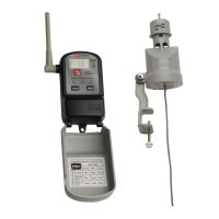
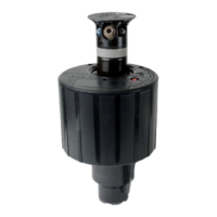
Integrated GDC Module
The Integrated GDC Module activation
type incorporates the GDC module attached
to the outside of the sprinkler body and
includes a DC latching solenoid for
activation of the control valve. The DC
latching solenoid shall be activated by the
Integrated GDC module with a momentary
low voltage pulse that moves the plunger
from the “OFF” position to the “ON”
position where it is maintained by a
permanent magnet in the solenoid. To
deactivate, a second momentary low-volt
pulse is applied to move the plunger from
the “ON” position to the “OFF” position.
The internal valve assembly shall be a
piston-type that vents to the atmosphere,
providing valve friction loss of less than 5
psi (0,34 Bar). The sprinkler shall be
designed to provide smooth valve closure in
excess of two seconds to minimize damage
resulting from surges and water hammer. All
valve seals shall be constructed of natural
rubber. The valve seat seal shall be
constructed of fabric-reinforced natural
rubber. The electric valve assembly shall
incorporate a 100-mesh stainless-steel screen
for the control water, preventing entry of
foreign materials into the pilot valve
assembly.
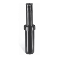
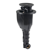
The sprinkler body and cap shall be
injection-molded from ABS – a corrosion-
proof, impact-resistant, UV-resistant, heavy-
duty, engineering-grade plastic material. The
cap and nozzle base shall incorporate a pull-
up feature that provides improved
serviceability of nozzles and riser. The
sprinkler shall have two plastic filter screens
– a top-serviceable coarse rock screen in the
body inlet sized to prevent entry of larger
foreign material from entering the body, and
a finer screen threaded into the riser, sized to
prevent foreign material from clogging the
nozzle.
The sprinkler shall have a riser/body seal
assembly that regulates flushing during pop-
up and retraction to clear any debris from
around the riser, and a heavy-duty, stainless-
steel spring to ensure positive retraction.
The riser is sealed by a durable, over-molded
urethane ring on the seal retainer. Sprinkler
flush rate shall not exceed 5 GPM (18,9
LPM).
The sprinkler shall be capable of identifying
the use of effluent water via a lavender-
colored marking. The sprinkler cap shall
indicate model designation, nozzle number
and manufacturing date code.
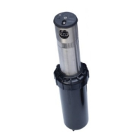
The sprinkler shall be of a pop-up design
with an overall height of 11 5/8” (295mm), a
body flange diameter of 7
5
/
8
” (194mm), a
cap diameter of 3
5
/
8
” (92mm) and a pop-up
stroke of 4
3/16” (106mm). The sprinkler
shall have a 1½” (40mm) ACME female-
threaded inlet. The sprinkler shall be capable
of covering ___ feet radius at ___ pounds
per square inch pressure with a discharge
rate of ___ gallons per minute.
The sprinkler shall be developed and
manufactured by an ISO 9001-certified
facility. The sprinkler shall be model
number __________ and shall be
manufactured by The Toro Company,
Irrigation Division.
 Loading...