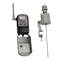
RainSensor Component Overview
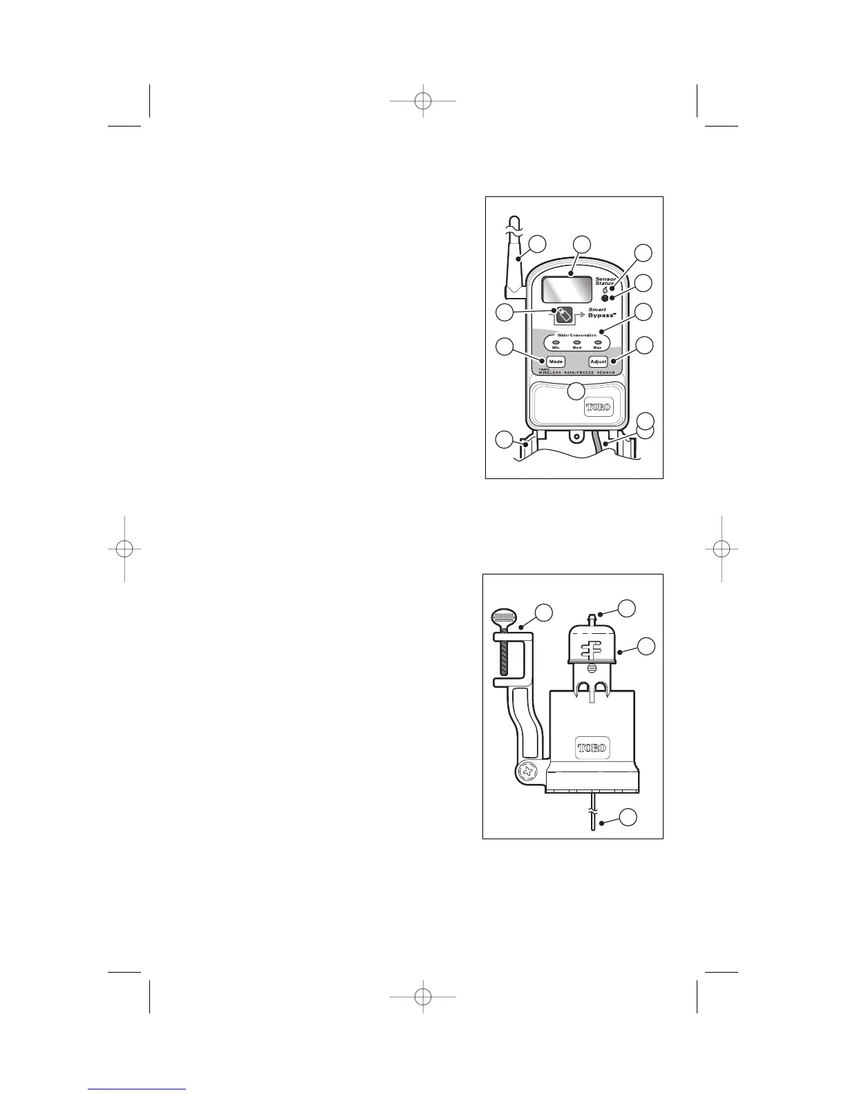
Receiver Module
1 -Weather-resistant Cover - Provides protection
from rain and dust. (Keep closed when not
using the receiver).
2 -Setup Button - Accesses the various setup
and operating features.
3 -Smart Bypass
TM
Button - Pressed to bypass
sensor control after it has been activated.
4 -Antenna - Position antenna straight up for
optimum signal reception.
5 -Liquid Crystal Display (LCD) - Provides visual
reference for setup and operation.
6 -Rain and Freeze Sensor Status Indicators -
Illuminate when the RainSensor is active and
watering is on hold.
7 -Water Conservation LED’s - Indicate the water
conservation level selected.
9 -Adjust Button - Pressed to adjust or select values within the setup and oper-
ating features.
10-Connection Cable - Multi-wire cable for connection to controller.
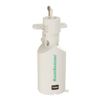
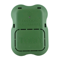
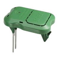
Sensor Module
1 -Test Spindle - Pressed to manually activate
the RainSensor system.
2 -Rain Threshold Adjustment - Adjustable cap
enables the rainfall threshold to be set for
1/8",1/4",1/2"or 3/4" of accumulated rainfall
before the sensor is activated.
3 -Quick-Clip
TM
Mounting Bracket - Simplifies
installation of the sensor module to a rain
gutter, edge of roof, fence post, etc.
4 -Antenna Wire - Position antenna straight down
for optimum signal transmission.
2
2
4
5
6
7
8
9
3
1
2
4
10
3
1
Figure 1
Figure 2