RemovingthePlasticCargo
Bed
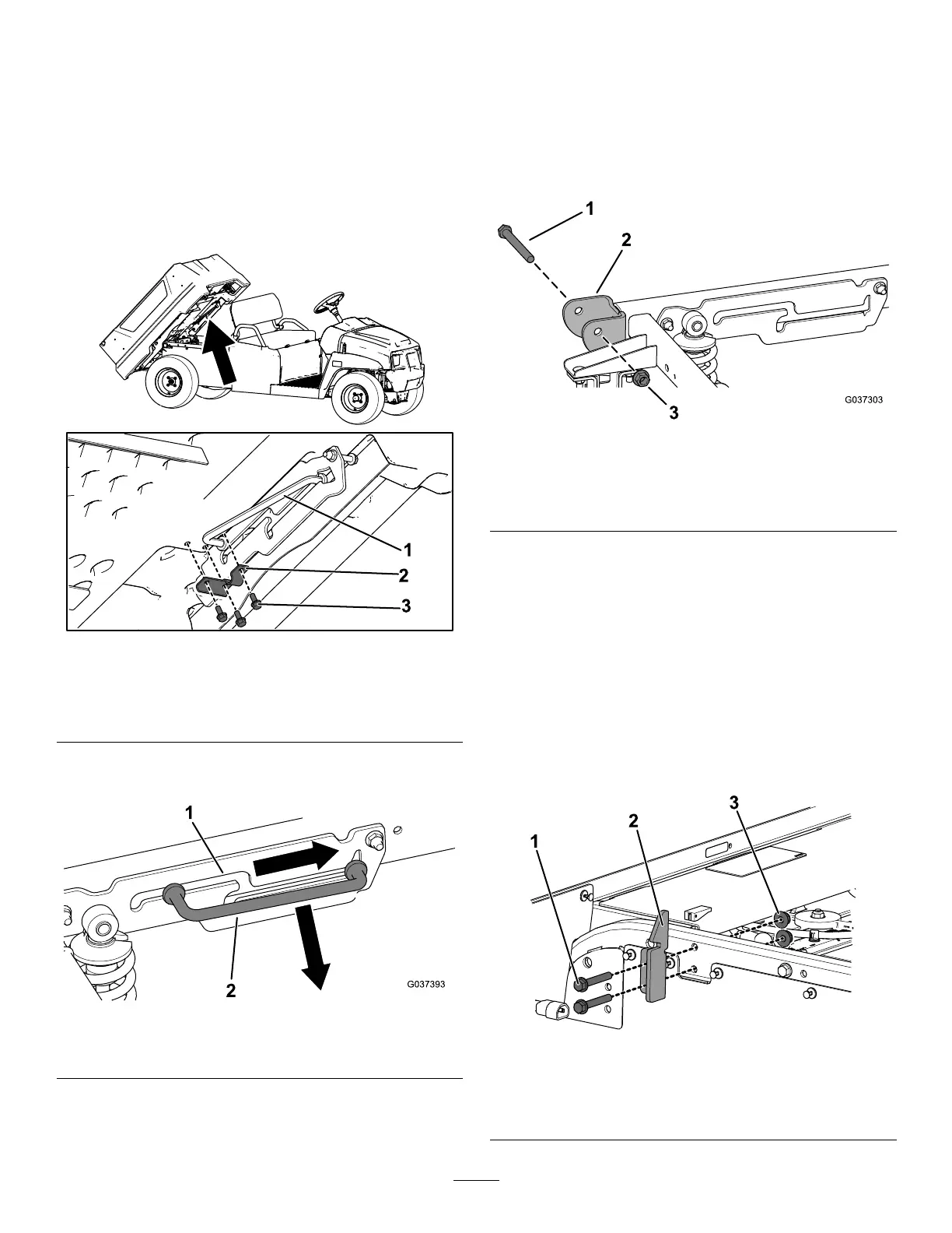
1.Usinganoverheadhoist,raisetheplasticcargo
bed.
2.Removethe3ange-headscrews(5/16x3/4
inch)andU-bracketfromtheproprod(Figure2).
Note:Retainthehardwaretoinstalltheplastic
cargobedinthefuture.
g244196
Figure2
1.Proprod
3.Flange-headscrew(5/16
x3/4inch)
2.U-bracket
3.Slidetheproprodforwardoutofthedetentslot
andremovetheproprod(Figure3).
g037393
Figure3
1.Detentslot2.Proprod
4.Usinganoverheadhoist,lowerthecargobed.
5.Removethe2pivotbolts(1/2x4-1/2inches)
and2locknuts(1/2inch)fromthepivotbracket
locatedattherearofthemachine(Figure4).
Note:Retainthehardwareforinstallation
oftheatbedassemblyin1inInstallingthe
Rear-FacingSeat(page4).
g037303
Figure4
1.Pivotbolt(1/2x4-1/2
inches)
3.Locknut(1/2inch)
2.Pivotbracket
6.Releasethecargo-bedlever,thenraiseand
removethecargobedusinganoverheadhoist.
7.Removethe2bedlatchesfromtheframeofthe
machinebyremovingthe4ange-headscrews
(3/8x2-1/2inches)and4nuts(3/8inch)as
showninFigure5.
Note:Retain2ange-headscrews(3/8x2-1/2
inches)and2nuts(3/8inch)forinstallation
oftheatbedassemblyinstep1inInstalling
theRear-FacingSeat(page4).Retainthe
remaininghardwaretoinstalltheplasticcargo
bedinthefuture.
g243577
Figure5
1.Flange-headscrew(3/8x
2-1/2inches)
3.Nut(3/8inch)
2.Bedlatch
3

 Loading...


