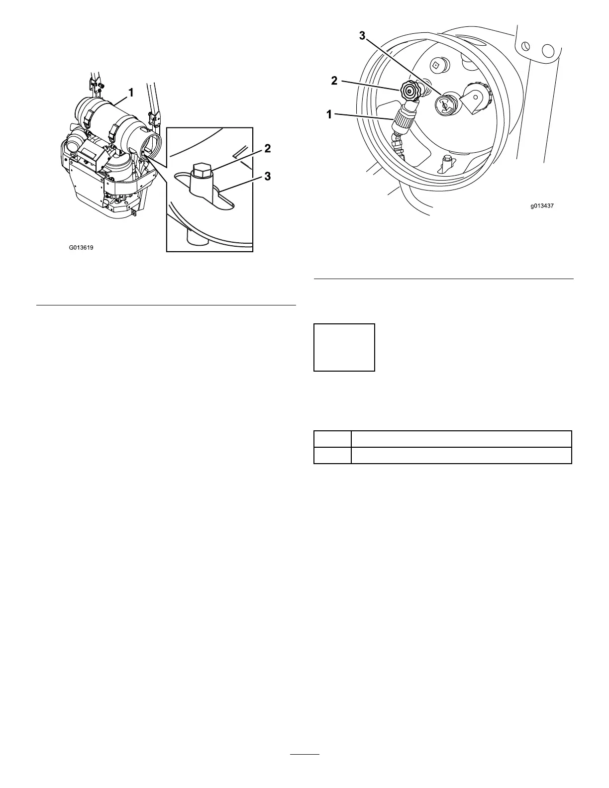
4.Alignthecenterholeoverthemountingpinthat
pointsstraightuponthemowerasshownin
Figure3.
Figure3
1.Tankcollar
3.Centerhole
2.Mountingpin
Important:Valvesandgaugesmaynotfunction
properlyiftheLPGtankisnotinstalled
correctly.
5.Latchthebracketsandmakesurethetankissecurely
fastenedtothemower.
6.Carefullyconnectthefuelhose.Makesurethehose
isnotkinked.
7.Slowlyopenthefuelvalvetoequalizethepressurein
thetank.Ifthefuelvalveisopenedtooquickly,the
pressurereliefvalveisequippedwithabackpressure
checkvalvethatwillshutoffthefuelsupply.Ifthis
happens,closethefuelvalvecompletelyandwait
veseconds.Slowlyopenthefuelvalve.
Figure4
1.LPGfuelhoseconnection
tting
3.Fuelgauge
2.Tankvalve
8.CheckforleaksasdescribedintheSafetysection
oftheOperator’smanual.
6
InstallingROPSHardware
Partsneededforthisprocedure:
1
Bolt(1/2x3-1/4inch)
1
Locknut(1/2inch)
Procedure
Installthebolt(1/2x3-1/4inch)andlocknut(1/2inch)
intotheopenholeintheROPS(RolloverProtection
System)(
Figure5).Thiswillpreventtherollbarfrom
hittingthecylinderwhenloweredtothedownposition..
3

 Loading...