Installation
8
m-3539
2
3
9
1
5
4
3
6
8
11
10
7
13
3
12
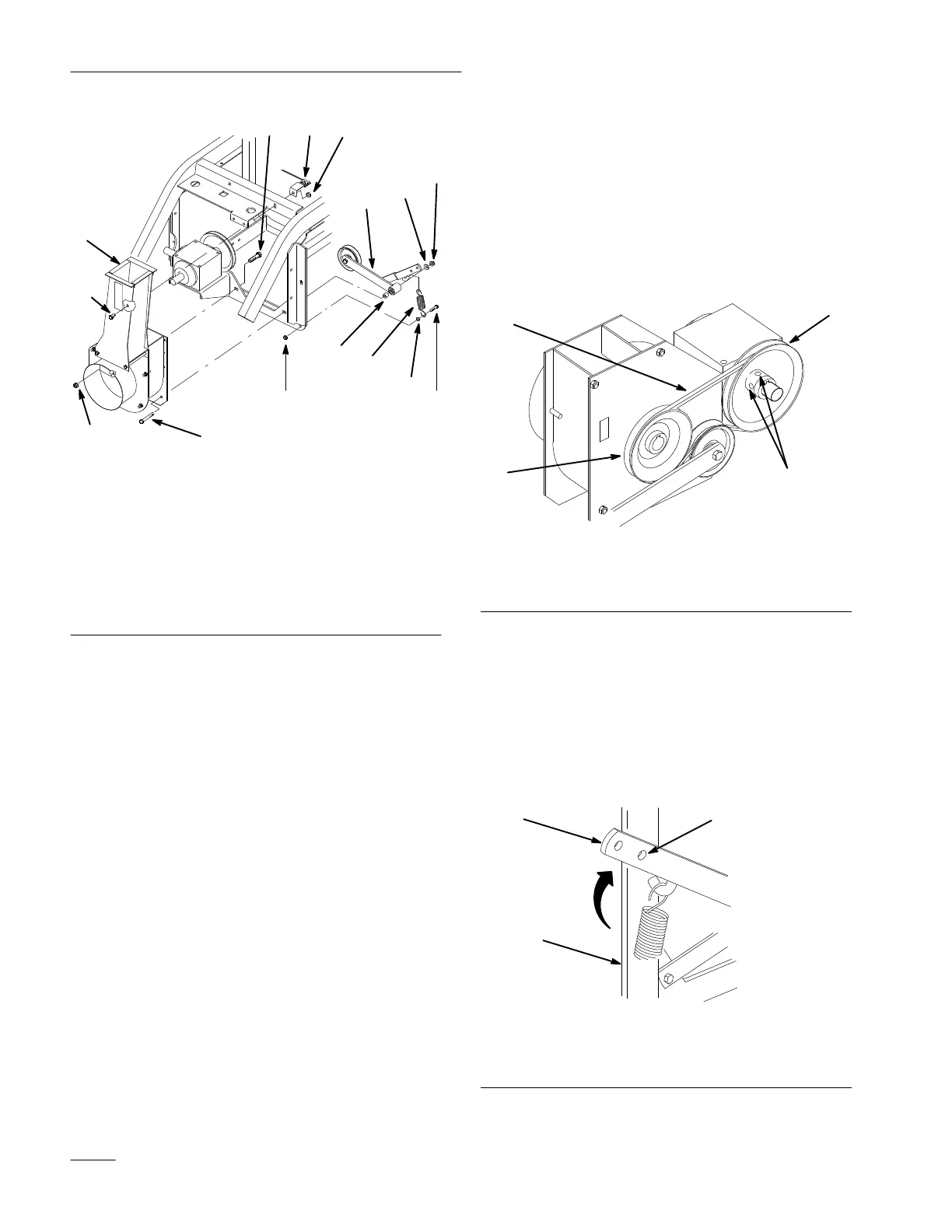
Figure 7
1. Blower
assembly
2.
Carriage bolt 3/8–16 x 1”
(25 mm)
3.
Flange locknut 3/8–16
4.
Bolt 3/8–16 x 2-3/4”
(70 mm)
5. Spacer
6.
Idler assembly
7. W
asher3/8” (9.5 mm)
8.
Bolt 5/16–18 x 1-1/4”
(32 mm)
9.
Nut 5/16–18
10.
Locknut 5/16–18
11. Spring
12.
Switch assembly
13. Bolt
3/8–16 x
3/4” (19 mm)
16. Using blower belt as a guide slide the PTO
pulley, in or out on gearbox shaft, to align with
blower pulley.
17. Torque setscrews to 15–18 ft.-lbs. (20–24 N
m)
18. Pull down on idler assembly, place belt above
idler pulley and release tension Use a straight
edge to check for belt alignment.
1
m-3550
3
2
4
Figure 8
1. PTO
pulley
2.
Blower pulley
3. Belt
4. Setscrew
19. Push up and hold the spring loaded idler arm,
behind blower, to relax pressure on blower belt
(Fig. 9).
20. If holes do not align, mark the idler arm hole
location onto the frame member. Center punch
and drill a 13/32” (11 mm) hole for the clevis pin
(Fig. 9).
m–3807
1
2
3
Figure 9
1. Idler
arm
2. Frame
3.
Mark and drill hole 13/32”
(1
1 mm)