Installation
10
Install
Hopper
1. Place hopper tilt brackets inside bumper with
tube weld away from the opening. Secure to
bumper with (4) 3/8–16 x 1” (26 mm) bolts and
(4) 3/8–16 flange locknuts (Fig. 12).
m–3803
1
2
3
4
5
Figure 12
1. Bumper
2. Tilt
bracket weld
3.
Bolt 3/8–16 x 1” (26 mm)
4.
Flange locknut 3/8–16
5.
Adjustment slot
2. Position bumper around top rear of frame and
secure in the center with (2) 1/2–13 x 1-1/4”
(32 mm) bolts and 1/2–13 locknuts (Fig. 13).
Secure to outer holes with (2) 1/2–13 x 2-3/4”
(57 mm) bolts and 1/2–13 locknuts.
3. Install ball stud to hopper frame and traction unit
frame tab with 5/16–18 locknut (Fig. 13).
3
m-3513
8
2
1
6
7
5
6
Figure 13
1. Bumper
2. Bolt
1/2–13 x 1-1/4”
(32 mm)
3.
Bolt 1/2–13 x 2-3/4”
(57 mm)
4.
Locknut 1/2–13
5.
Ball stud
6.
Locknut 5/16–18
7.
Gas spring
8.
Safety clip
4. Secure hopper latch to the frame with 1/2”–13 x
1” (25 mm) bolts and 1/2”–13 locknut (Fig. 14).
1
2
m-3554
3
4
5
Figure 14
1. Hopper
latch
2.
Bolt 1/2”–13 x 1” (25 MM)
3. W
asher 1/2” (13 mm)
4.
Locknut 1/2”–13
5.
Front of unit
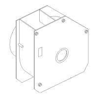
5. Place hopper assembly onto frame and align
with holes in bumper mounts. Insert (2) clevis
pins and secure with hairpin cotters (Fig. 15).
6. Adjust tilt brackets in slots (Fig. 12) so chute
opening and hopper opening align at the front.
7. Snap gas spring rod ends over ball stud at frame
and hopper. Secure with safety clips (Fig. 13).
Note: Rod end of gas spring must face the
rear and attach to the traction unit
frame.
1
m-3565
3
2
Figure 15
1. Hopper
frame assembly
2.
Clevis pin 1/2 x 1-1/2”
(38 mm)
3.
Hairpin cotter–large