EasyManua.ls Logo

Toshiba 2857 DB - User Manual

Toshiba 2857 DB
10 pages
Print Icon
To Next Page IconTo Next Page
Loading...
1
TOSHIBA 2857 DB
General Information
Chassis: C5SS
A401 23426393 Back Cover
C440 24082482 PF, 7000pF, ±3%, 1500V
C441 24082669 PF, 0.33µF, 250V
C442 24082672 PF, 0.43µF, 250V
C444 24082519 PF, 6200pF, ±3%, 1800V
C463 24212222 CD, 2200pF, ±10%
C801 24082374 PE, 0.22µF, AC250V
C805 24092281 CD, 4700pF, ±20%, AC250V
C806 24092281 CD, 4700pF, ±20%, AC250V
R801 24009954 Metal-Glazed Resistor, 2.2M ohm, 1/2W
R808 24019340 PTC Thermistor, 18 ohm, 290V
R810 24007489 Cement, 3 ohm, 20W
R811 24568271 Cement, 270 ohm, 7W
R824 24569689 Cement, 6.8 ohm, 10W
R841 24531120 FR, 12 ohm, 1/2W
R899 24005007 Metal-Glazed Resistor, 8.2M ohm, 1W
L462 ------------- DY, Supplied with V901
L901 23200276 Coil, Degaussing, TSB-2330BR
T401 23224336 Transformer, Horiz. Drive, TLN1083
T461 23236447 Transformer, Flyback, TFB4115AR
T801 23211891 Line Filter, TRF3164
T803 23217301 Transformer, Converter, TPW3336AR
Q404 A6872801 Transistor, 2SD2253(FA)
Q801 23905084 IC, STR-S6709
Q826 A8643106 Photo Coupler, TLP621(GR)
D801 23316795 Diode, D6SB60L,F05
F470 23144873 Fuse, 1.0A
F801 23144898 Fuse, 3.15A
P801 23372012 Power Cord
V901A 23902891 Socket, CRT, 10P
V901 23312645 Picture Tube, A66EAK252X21
Recommended Safety Parts
Item Part No. Description
X-RAY RADIATION PRECAUTION
1. The E.H.T. must be checked every time the
receiver is serviced to ensure that the C.R.T.
does not emit X-ray radiation as result of
excessive E.H.T. voltage. The nominal E.H.T.
for this receiver is 31.5 kV at zero beam
current (minimum brightness) operating at
240V a.c. The maximum E.H.T. voltage
permissible in any operating circumstances
must not exceed 32.0 kV. When checking the
E.H.T., use the ‘High Voltage Check’ proce-
dure, using an accurate E.H.T. voltmeter.
2. The only source of X-RAY radiation in this
receiver is the C.R.T. To prevent X-ray
radiation, the replacement C.R.T. must be
identical to the original fitted as specified in
the Parts List.
3. Some components used in this receiver have
safety related characteristics preventing the
C.R.T. from emitting X-ray radiation. For
continued safety, replacement component
should only be made after referring the
Product Safety Notice below.
SAFETY PRECAUTION
1. This receiver has a nominal working E.H.T.
voltage of 28.5 kV. Extreme caution should be
exercised when working on the receiver with
the back removed. Do not attempt to service
this receiver if you are not conversant with the
precautions and procedures for working on
high voltage equipment. When handling or
working on the C.R.T., always discharge the
anode to the receiver chassis before remov-
ing the anode cap The C.R.T., if broken, will
violently expel glass fragments. Use shatter
proof goggles and take extreme care while
handling. Do not hold the C.R.T. by the neck
as this is a very dangerous practice.
TEST SIGNAL SELECTION
Every pressing of button changes the test
patterns on screen as described below in
SERVICE MODE.
Signal off NTSC signals (14 patterns)
PAL signals (14 patterns)
About inside signal: The inside signal is output
at video input terminal from QA01, and is not
output with the pin inserted into terminal.
(Single color signal can be output.)
Signals
Red single colour
Green single colour
Blue single colour
Black single colour
White single colour
Picture
Using method
Purity and White uniformity of CRT
Red single colour.
Stopping G and B output of Q501
Green single colour.
Stopping R and B output of Q501
Blue single colour.
Stopping R and G output of Q501
Black single colour.
Making black signal of approx. 1Vp-p in QA01
White single colour.
Making white signal of approx. 1Vp-p in QA01
Signals
W/B adjustment
Picture
Using method
White balance adjustment
White .
White balance adjustment/check in light area
Black part.
White balance adjustment/check in dark area.
Making. approx. 1Vp-p signal in QA01.
Signals
Black cross-bar
White cross-bar
2. It is essential that to maintain the safety of the
customer all cable forms be replaced exactly
as supplied from factory.
3. A small part of the chassis used in this
receiver is, when operating, at approximately
half mains potential at all times. It is therefore
essential in the interest of safety that when
serving or connecting any test equipment the
receiver should be supplied via a suitable
isolating transformer of adequate rating.
4. Replace blown fuses within the receiver with
the fuse specified in the parts list.
5. When replacing wires or components to
terminals or tags, wind the leads around the
terminal before soldering. When replacing
safety components identified by the interna-
tional hazard symbols on the circuit diagram
and parts list, it must be a Toshiba approved
type and must be mounted as the original.
6. Keep wires away from high temperature
components.
PRODUCT SAFETY NOTICE
Many electrical and mechanical components in
this chassis have special safety-related
characteristics. These characteristics are often
passed unnoticed by a visual inspection and the
X-ray radiation protection afforded by them
cannot necessarily be obtained by using
replacements rated at higher voltages or
wattage, etc. Components which have these
special safety characteristics in this manual and
its supplements are identified by the interna-
tional hazard symbols on the schematic diagram
and parts list. Before replacing any of these
components read the parts list in this manual
carefully. Substitute replacement components
which do not have the same safety characteris-
tics as specified in the parts list may create X-
ray radiation.
1. ENTERING TO SERVICE MODE
1) Press button once on Remote Control.
2) Press button again to keep pressing.
3) Keep pressing the button, press MENU
button on TV set.
RCUT S
32H
(Service mode dIsplay)
2. SELECTING THE ADJUSTING ITEMS
Every pressing of CHANNEL button changes
the adjustment items in the following order.
( button for reverse order.)
3. ADJUSTING THE DATA
Pressing of VOLUME or button will change
the value of data in the range from 00 to FF. The
variable range depends on the adjusting item.
4. NORMAL OPERATION ON THE SERVICE
MODE
Press MENU button on TV.
Adjustment mode Service mode
RCUT Address S
32H Data
5. EXIT FROM SERVICE MODE
Press POWER button on the remote control to
turn off the TV once.
OTHER SERVICE FUNCTION
The following key entry during display of
adjustment menu provides special functions.
Press
Press
Service Mode General
Instructions
Picture
Using method
Picture position (horizontal, vertical and slant) in
CRT adjustment.
Making approx. 1 Vp-p signal in QA01.
Signals
Black cross-hatch
White cross-hatch
Picture
Using method
Convergence and vertical amplitude adjustment
Making approx. 1 Vp-p signal in QA01.
Signals
Black cross-dot
White cross-dot
Picture
Using method
Convergence adjustment
Making approx. 1Vp-p signal in QA01.
Signals
H signal (Left, right, white)
H signal (Left, right, black)
Picture
Using method
For checking (of purity drift) of white uniformity
of CRT H signal (Left, right, white).
Check in light area.
H signal (Left, right, black).
Check in dark area.
The adjustment will be the best, if the time when
unevenness of color in light area occurs, is a
little longer than that in dark area.
Making approx. 1Vp-p signal in QA01.
Matrix
Item See Model Book
Adjustments (Not Service mode) .................................................................. 2152 DB 5
Question and Answer IconNeed help?

Do you have a question about the Toshiba 2857 DB and is the answer not in the manual?

Summary

General Information

Safety Precautions

Covers X-ray radiation, general safety, and product safety notices for servicing.

Service Mode Operations

Accessing and Adjusting Settings

Details on entering service mode, selecting items, and adjusting data values.

Normal Use and Test Signals

Guidance on normal operation, exiting, test signals, and other service functions.

Specific Service Adjustments

Initialization, Brightness, and White Balance

Procedures for QA02 memory initialization, sub-brightness, and white balance adjustments.

Cutoff, Drive, and Picture Positioning

Adjustments for cutoff, drive, horizontal/vertical position, and amplitude for picture tuning.

Diagnostics and Data Reference

Covers self-diagnostic functions and provides reference for adjustment procedures and conditions.

Overview

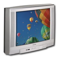
This document describes the TOSHIBA 2857 DB, a television receiver, providing detailed information on its general operation, service mode, and various PCB diagrams.

Function Description

The TOSHIBA 2857 DB is a television receiver designed for general home use. It incorporates features for picture and sound processing, remote control operation, and various adjustments to optimize viewing experience. The device supports multiple video input types and includes a text/RGB switching unit.

Important Technical Specifications

Chassis: CS5S Matrix: The matrix for adjustments is provided, indicating the item, EEP (address), and value of initiating data. For example, H OUT is at EEP 00H with an initiating value of 0 (OFF). V SIZE is at EEP 01H with an initiating value of 0 (OFF). SUB CONTRAST (MAX 3 MODE) is at EEP 08H with an initiating value of 0 (OFF). SUB COLOR (PAL) is at EEP 0AH with an initiating value of 0 (OFF). SUB COLOR (NTSC) is at EEP 0BH with an initiating value of 0 (OFF). SUB COLOR (SECAM) is at EEP 0CH with an initiating value of 0 (OFF). SUB BRIGHT is at EEP 0DH with an initiating value of 0 (OFF). SUB TINT is at EEP 0EH with an initiating value of 0 (OFF). SUB VOL is at EEP 0FH with an initiating value of 0 (OFF). V POS is at EEP 30H with an initiating value of 0 (OFF). H POS is at EEP 31H with an initiating value of 0 (OFF). V LINEARITY is at EEP 32H with an initiating value of 0 (OFF). V H CORRECTION is at EEP 33H with an initiating value of 0 (OFF). V SW (COMPENSATION) is at EEP 34H with an initiating value of 0 (OFF). E/W PARABOLA is at EEP 35H with an initiating value of 0 (OFF). E/W TRAPEZIUM is at EEP 36H with an initiating value of 0 (OFF). E/W CORRECTION is at EEP 37H with an initiating value of 0 (OFF). SECAM B-Y is at EEP 38H with an initiating value of 0 (OFF). SECAM R-Y is at EEP 39H with an initiating value of 0 (OFF).

The device includes a Comb & Delay PCB with components like the TA8772AN 1H DEL & MATRIX IC (QQ02) and the TC9090N IC (QZ01). The AV PCB handles audio and video inputs and outputs, including connections for various external devices. The CRT PCB manages the display tube, with components for horizontal and vertical deflection, and color processing. The Signal Processing Diagram illustrates the flow of video and audio signals, including PAL, COMB+1H DL, and PRO-LOGIC UNIT sections. The Power & Deflection Diagram details the power supply and deflection circuits, crucial for the operation of the CRT.

Usage Features

Remote Control Operation: The television is primarily operated via a remote control.

  1. ENTERING TO SERVICE MODE:
    • Press the MUTE button on the remote control.
    • Press the MUTE button again and keep pressing.
    • While keeping the MUTE button pressed, press the MENU button on the TV.
    • RCUT is ON.
    • RSDN is ON.
  2. SELECTING THE ADJUSTING ITEMS:
    • Each time the CH+ or CH- button is pressed, the adjusting item changes in the following order: button for reverse (RSDN).
  3. ADJUSTING THE DATA:
    • Pressing VOLUME + or VOLUME - will change the data value. The RCUT and RSDN variable range depends on the adjusting item.
  4. NORMAL OPERATION ON THE SERVICE MODE:
    • Press the MENU button on the TV.
  5. EXIT FROM SERVICE MODE:
    • Press the POWER button on the remote control to turn off the TV.

Other Service Function: The following key entry during display of adjustment menu provides special functions:

  • Test Signal Display: Pressing the TEST1 button on the remote control displays various test patterns (PAL signals, NTSC signals, and a white cross-hatch).
    • PAL signals ( NTSC signals):
      • Red single colour
      • Green single colour
      • Blue single colour
      • White single colour
      • Picture
    • White cross-hatch:
      • Red single colour
      • Green single colour
      • Blue single colour
      • White single colour
      • Picture
  • W/B Adjustment:
    • Using MUTE and VOLUME + or VOLUME -:
      • White balance adjustment
      • White balance adjustment/check in light area
      • Black part
      • White balance adjustment/check in dark area
      • Black cross-bar
      • White cross-bar
  • Picture:
    • Using MUTE and VOLUME + or VOLUME - to adjust purity and uniformity of CRT.
    • Red single colour
    • Green single colour
    • Blue single colour
    • White single colour
    • Picture
  • Using method (horizontal, vertical and start):
    • Red single colour
    • Green single colour
    • Blue single colour
    • White single colour
    • Picture
  • Using method (convergence adjustment):
    • Red single colour
    • Green single colour
    • Blue single colour
    • White single colour
    • Picture
  • Using method (purity and uniformity of CRT):
    • Red single colour
    • Green single colour
    • Blue single colour
    • White single colour
    • Picture

Service Mode Adjustments: The service mode allows for detailed adjustments of various parameters:

  • Initialisation of QAO2 (Memory):
    • Sets the initial values for all adjustment data.
    • Press MUTE on the remote control.
    • Press MUTE again and keep pressing.
    • While keeping MUTE pressed, press MENU on the TV.
    • RCUT is ON.
    • Press MUTE on the remote control again.
    • QAO2 has been completed.
  • Automatic Search Memory:
    • Press MUTE on the remote control.
    • Press MUTE again and keep pressing.
    • While keeping MUTE pressed, press MENU on the TV.
    • RCUT is ON.
    • Press MUTE on the remote control again.
    • QAO2 has been completed.
  • White Balance Adjustment:
    • Adjusts the picture height until the vertical retrace appears.
    • Press MUTE on the remote control.
    • Press MUTE again and keep pressing.
    • While keeping MUTE pressed, press MENU on the TV.
    • RCUT is ON.
    • Press MUTE on the remote control again.
    • QAO2 has been completed.
  • Drive Adjustment:
    • Adjusts the picture height until the vertical retrace appears.
    • Press MUTE on the remote control.
    • Press MUTE again and keep pressing.
    • While keeping MUTE pressed, press MENU on the TV.
    • RCUT is ON.
    • Press MUTE on the remote control again.
    • QAO2 has been completed.
  • Self Diagnostic Function:
    • Displays the self-diagnostic data during display of the adjustment menu.
    • The DIAG button on the remote control displays the self-diagnostic data.
    • The DIAG button displays the following: SELF CHECK, EEPROM, BLOCK, V1, V2, V3, V4, V5, V6, V7, V8, V9, V10, V11, V12, V13, V14, V15, V16, V17, V18, V19, V20, V21, V22, V23, V24, V25, V26, V27, V28, V29, V30, V31, V32, V33, V34, V35, V36, V37, V38, V39, V40, V41, V42, V43, V44, V45, V46, V47, V48, V49, V50, V51, V52, V53, V54, V55, V56, V57, V58, V59, V60, V61, V62, V63, V64, V65, V66, V67, V68, V69, V70, V71, V72, V73, V74, V75, V76, V77, V78, V79, V80, V81, V82, V83, V84, V85, V86, V87, V88, V89, V90, V91, V92, V93, V94, V95, V96, V97, V98, V99, V100, V101, V102, V103, V104, V105, V106, V107, V108, V109, V110, V111, V112, V113, V114, V115, V116, V117, V118, V119, V120, V121, V122, V123, V124, V125, V126, V127, V128, V129, V130, V131, V132, V133, V134, V135, V136, V137, V138, V139, V140, V141, V142, V143, V144, V145, V146, V147, V148, V149, V150, V151, V152, V153, V154, V155, V156, V157, V158, V159, V160, V161, V162, V163, V164, V165, V166, V167, V168, V169, V170, V171, V172, V173, V174, V175, V176, V177, V178, V179, V180, V181, V182, V183, V184, V185, V186, V187, V188, V189, V190, V191, V192, V193, V194, V195, V196, V197, V198, V199, V200, V201, V202, V203, V204, V205, V206, V207, V208, V209, V210, V211, V212, V213, V214, V215, V216, V217, V218, V219, V220, V221, V222, V223, V224, V225, V226, V227, V228, V229, V230, V231, V232, V233, V234, V235, V236, V237, V238, V239, V240, V241, V242, V243, V244, V245, V246, V247, V248, V249, V250, V251, V252, V253, V254, V255.

Maintenance Features

X-RAY RADIATION PRECAUTION:

  1. The E.H.T must be checked every time the unit is serviced. If the E.H.T. exceeds 27.5 KV, do not use the unit.
  2. The E.H.T. must be checked at regular intervals for this receiver.
  3. The E.H.T. must be checked at 24.0 KV.
  4. The maximum E.H.T. voltage must not exceed 27.5 KV.
  5. Only use the high voltage check probe.
  6. The E.H.T. source of X-ray radiation in this receiver is the CRT.
  7. The replacement CRT must be identical to the original.
  8. The replacement parts must be identical to the original.
  9. The replacement parts must be identical to the original.
  10. The replacement parts must be identical to the original.

Product Safety Notice:

  1. This receiver has a normal working E.H.T. voltage of 24.0 KV.
  2. This receiver is equipped with a safety interlock.
  3. This receiver is equipped with a safety interlock.
  4. This receiver is equipped with a safety interlock.
  5. This receiver is equipped with a safety interlock.
  6. This receiver is equipped with a safety interlock.
  7. This receiver is equipped with a safety interlock.
  8. This receiver is equipped with a safety interlock.
  9. This receiver is equipped with a safety interlock.
  10. This receiver is equipped with a safety interlock.

Product Safety:

  1. Many electrical and mechanical components in this chassis have special safety-related characteristics.
  2. These characteristics are often passed unnoticed by a visual inspection and the protection they give cannot be readily ascertained.
  3. Any component having such characteristics is identified by the international safety symbol.
  4. Before replacing any of these components, read the schematic diagram carefully.
  5. The use of a substitute component that does not have the same safety characteristics as the original may create a shock, fire, or other hazards.

Toshiba 2857 DB Specifications

General IconGeneral
BrandToshiba
Model2857 DB
CategoryTV
LanguageEnglish

Related product manuals