EasyManua.ls Logo

Toshiba 2857DD User Manual

Toshiba 2857DD
54 pages
To Next Page IconTo Next Page
Page #1 background imageLoading...
Page #1 background image
TOSHIBA
FILE
NO.
030-9530
SERVICE
MANUAL
COLOUR
TELEVISION
C5SS
Chassis
285/DD
Question and Answer IconNeed help?

Do you have a question about the Toshiba 2857DD and is the answer not in the manual?

Toshiba 2857DD Specifications

General IconGeneral
Display TechnologyCRT
Aspect Ratio4:3
TunerNTSC
Screen Size28 inches
InputsComposite, S-Video

Summary

Toshiba Service Manual Safety Instructions

X-Ray Radiation Precautions

Precautions to prevent X-ray radiation emission from the CRT.

Safety Precautions

General safety measures to be observed during servicing.

Product Safety Notice

Notice regarding safety-related components and their replacement.

Front Controls and Rear Views

Toshiba Remote Hand Held Unit

Remote Key Assignment

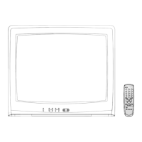
Detailed listing of remote control buttons and their functions.

Circuit Block Diagram Overview

Installation and Service Adjustments

General Information for Installation

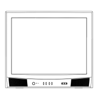
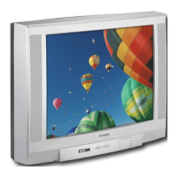
Basic information for setting up and initial checks of the receiver.

Automatic Degaussing Process

Explanation of the automatic degaussing coil function.

High Voltage Check Procedure

Instructions for checking the high voltage output.

Focus Adjustment Method

Procedure for adjusting the focus control on the flyback transformer.

Service Mode General Instructions

Entering Service Mode

Step-by-step guide to access the service mode.

Displaying the Adjustment Menu

How to view the adjustment menu on the TV screen.

Selecting Adjustment Items

Method for navigating through different adjustment items.

Adjusting Data Values

How to modify data values for adjustments using volume buttons.

Exiting Service Mode

Procedure to turn off the TV and exit service mode.

Other Service Functions

Test Signal Selection

Service Mode Adjustments

QA02 Memory Initialization

Procedure for initializing the QA02 memory IC after replacement.

Sub-Brightness Adjustment

Adjusting brightness correction (BRTC) for optimal picture.

Horizontal Position Adjustment (HPOS)

Procedure for setting the horizontal picture position.

Vertical Position Adjustment (VPOS)

Procedure for setting the vertical picture position.

Vertical Amplitude Adjustment (HIT)

Procedure for adjusting the vertical picture amplitude.

Service Mode Adjustments (Continued)

White Balance Adjustment

Procedure for adjusting white balance.

Cutoff Adjustments (RCUT, GCUT, BCUT)

Adjusting cutoff levels for Red, Green, and Blue.

Drive Adjustments (GDRV, BDRV)

Adjusting drive levels for Green and Blue.

Self Diagnostic Function

How to perform self-diagnosis and interpret results.

Video-Chroma System Adjustments

[COLP] Adjustment

Factory adjustment for PAL color signal output amplitude.

Cutoff and Screen VR Adjustment

Adjusting cutoff and screen VR for R, G, B lines.

Cutoff and Drive Balance Adjustment

Alternately adjusting cutoff and drive for white balance.

[BELL] Filter Adjustment

Adjusting the BELL filter for flat waveform output.

[SRY] SECAM R-Y Black Label Adjustment

Adjusting SECAM R-Y signal level for black label.

[SBY] SECAM R-Y Black Label Adjustment

Adjusting SECAM R-Y signal level for black label.

[COLS] Sub-color Center SECAM Adjustment

Adjusting SECAM sub-color center amplitude.

Adjustment Procedure Details

Adjustment Parts and Bus Control Items

Details on parts and bus control items for adjustments.

Multi Bus E2PROM Address and Adjusting Table

How to Make Chassis Stand for Repair

Disconnect Degausser Coil Wires

Step 1: Disconnect speaker lead wires from degausser coil.

Chassis Removal from Front Mask

Step 2: Gently pull out the chassis from the front mask.

Chassis Hooking into Front Mask Slit

Step 3: Secure the chassis by hooking it into the front mask slit.

Cabinet Replacement Parts List

Chassis Replacement Parts List

Signal Board PB5747 Component Layout

Power/Def Board PB5748 Component Layout

Back Terminal/AV Board PB5657X Component Layout

CRT Drive/DSM Board PB5659X Component Layout

Pro-Logic Board PB5665 Component Layout

Text/RGB SW Board PB5662X Component Layout

Terminal View of Transistors

Diagrams showing the pin configurations of various transistors.

Schematic Diagram (1/4)

Signal Board Connections

Connections for the Signal Board.

PAL Comb/1H DL Unit

Schematic section for PAL Comb/1H DL Unit.

Pro-Logic Unit Connections

Connections for the Pro-Logic Unit.

Text/RGB SW Unit Connections

Connections for the Text/RGB SW Unit.

Text/RGB SW Unit Schematic and Component Values

Resistor, Capacitor, and Inductor Value Expression

Explanation of how component values are represented in the schematic.

Toshiba Television Specifications

Related product manuals