BN interface Installation Manual
3
-EN
Introduction
Overview
The BN interface refers to equipment used for controlling Building Management Systems (Procured locally) and air conditioners
“TU2C-LINK Uh Line (hereinafter, referred to as Uh Line) compatible models” through communications via a network to enable
central control.
Included Items
Specifications
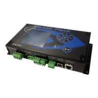
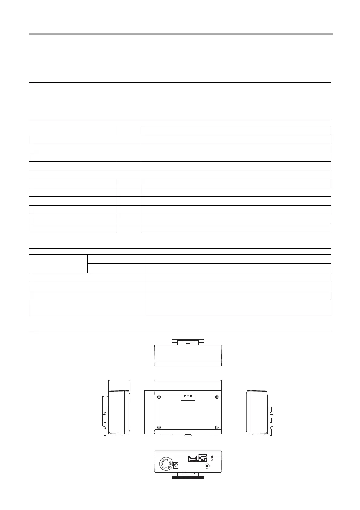
External View (BN interface equipment)
Component Q'ty Remarks
BN interface equipment 1
Power adapter 1 BN interface power supply (model name: UI318-0526) (not include Power Cable)
Pin terminal 2 Uh Line caulked connectors
Mounting bracket (DIN rail) 1 Use screws to secure the unit in locations without DIN rails (walls, etc.)
Screws (M4 x 12) 2 For securing the DIN rails
Rubber feet 4 For levelling the unit
Screws (M3 x 8) 4 For securing the rubber feet to the unit
Installation Manual 1 This manual
License Agreement 1
License Information 1
Tie-wrap 1
Power supply
Rated voltage 220-240 VAC 50/60 Hz
Power consumption 3 W
Operating temperature range 0°C to 40°C, 10% to 80% RH (no condensation)
Storage temperature range
−
10°C to +60°C, 10% to 90% RH (no condensation)
Dimensions Width 140 mm x Height 90 mm x Depth 45 mm
Mass BN interface 260 g
Power adapter 140 g
䣒䣑䣙䣇䣔 䣎䣋䣐䣍䢪䣗䣪䢫 䣅䣒䣗
(5525
 Loading...