EasyManua.ls Logo

Toshiba MCY-MHP0404HS-E User Manual

Toshiba MCY-MHP0404HS-E
187 pages
To Next Page IconTo Next Page
Page #1 background imageLoading...
Page #1 background image
FILE NO. A10-1510
SERVICE MANUAL
AIR-CONDITIONER (MULTI TYPE)
O
UTDOOR UNIT
Model name:
This service manual provides relevant explanations about new outdoor unit.
Please refer to the following service manuals for each indoor units.
MCY-MHP0404HS(J)-E/0504HS(J)-E/0604HS(J)-E
MCY-MHP0404HS-TR/0504HS-TR/0604HS-TR
MCY-MHP0404HS(J)/0504HS(J)/0604HS(J)
MCY-MHP0404HS-ID/0504HS-ID/0604HS-ID
MCY-MHP0404HS-A/0504HS-A/0604HS-A
Service Manual No.
<4-way Cassette Type>
(MMU-AP****H) A08-004
(MMU-AP***4HP*) (Made in Thailand model) SVM-13011
<2-way Cassette Type>
(MMU-AP****WH*) A10-007
<Concealed Duct Standard Type>
(MMD-AP***6BHP*) (Made in Thailand model) SVM-14069
<Slim Duct Type>
(MMD-AP024, A0274SPH*) A12-005
<Concealed Duct High Static Pressure Type>
(MMD-AP***6HP*) (Made in Thailand model) SVM-15032
<High-wall Type>
(MMK-AP***4MH*) (Made in Thailand model) SVM-09059
(MMK-AP***3H*) (Made in Thailand model) A10-034
<Console Type>
(MML-AP****NH*) (Made in Thailand model) SVM-11036
<Ceiling Type>
(MMC-AP***7HP*) (Made in Thailand model) SVM-13085
<Floor Standing Type>
(MMF-AP***6H*) A10-1420
<Other indoor units>
(MM*-AP*****H*) A10-033
A10-1510.indb1A10-1510.indb1 2016/04/0817:20:032016/04/0817:20:03
AMP Air Conditioning
www.ampair.co.uk | sales@ampair.co.uk

Table of Contents

Question and Answer IconNeed help?

Do you have a question about the Toshiba MCY-MHP0404HS-E and is the answer not in the manual?
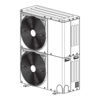
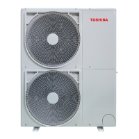
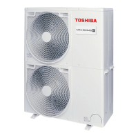
Toshiba MCY-MHP0404HS-E Specifications

General IconGeneral
Cooling Capacity (kW)4.0
Heating Capacity (kW)4.5
Power Supply220-240V, 50Hz, 1 Phase
Cooling Capacity4.0 kW
Heating Capacity4.5 kW

Summary

SERVICE MANUAL

Precautions for safety

Specifications

Wiring diagram

Parts rating

Parts layout in outdoor unit

Parts layout in inverter assembly

Interface P.C. board (MCC-1639)

Inverter P.C. board for compressor (MCC-1647) A3-IPDU

Fan motor IPDU (MCC-1597) for upper fan and lower fan

Noise filter (MCC-1551)

Refrigerant piping systematic drawing

Control outline

Outdoor unit controls

Explains the operational logic and control mechanisms for the outdoor unit.

Applied control for outdoor unit

Indoor unit setup method for priority indoor unit mode

Optional P.C. board of outdoor unit installation

Optional control P.C. boards functions

Power peak-cut control (standard)

Power peak-cut control (extended)

External master ON / OFF control

Night operation (sound reduction) control

Operation mode selection control

Error / Operation output

Test operation

Check items before test operation (before powering-on)

Lists essential checks to perform before initiating test operations for electric wiring.

Address setup

Address setup and check procedure

Step-by-step guide for setting and verifying unit addresses.

Address setting procedure 1

Procedure for automatic address setting, typically for single refrigerant lines.

Address setting procedure 2

Procedure for setting addresses, often involving manual switch adjustments for multiple lines.

Troubleshooting

Overview

Provides a general overview of troubleshooting procedures and common issues.

Troubleshooting method

General methods for identifying trouble sites using diagnostic displays.

List of Check Codes (Indoor Unit)

A comprehensive list of check codes detected by indoor units and their troubleshooting.

List of Check Codes (Outdoor Unit)

Lists check codes detected by the outdoor unit's interface P.C. board and their troubleshooting.

Troubleshooting based on information displayed on remote controller

Guide to interpreting and troubleshooting based on information shown on the main remote controller.

Diagnosis procedure for each check code

Signal transmission trouble on the remote controller

Troubleshooting steps for signal transmission issues between the remote controller and indoor units.

Communication trouble between the indoor unit and remote controller (detected on the indoor unit)

Diagnoses communication problems between indoor units and remote controllers.

Indoor / Outdoor communication circuit trouble (Detected at indoor side)

Troubleshooting for communication failures between indoor and outdoor units detected at the indoor side.

Automatic address start trouble

Troubleshoots issues during the automatic address setting process.

No corresponding indoor unit during automatic-address

Addresses situations where no indoor unit is found during automatic address setup.

High-pressure protective operation

Troubleshooting flowchart for high-pressure protective operation events.

Compressor breakdown

Troubleshooting steps for compressor breakdown, including power and circuit issues.

Low-pressure protective operation

Diagnoses and resolves issues related to low-pressure protective operation.

7-segment display function

Checking procedure to be followed in event of abnormal shutdown

Steps to check the 7-segment display for error codes during abnormal system shutdowns.

Outdoor unit parts replacement methods

Step 12: Compressor replacement

Detailed steps for removing and replacing the compressor, including refrigerant handling and brazing.

Step 13: Compressor installation

Procedures for installing the new compressor, including vacuuming and refrigerant charging.

P.C. board exchange procedures

Exploded diagram / parts list

WARNINGS ON REFRIGERANT LEAKAGE

Related product manuals