DISASSEMBLY INSTRUCTIONS
B1-2
1.
2.
3.
4.
5.
6.
7.
8.
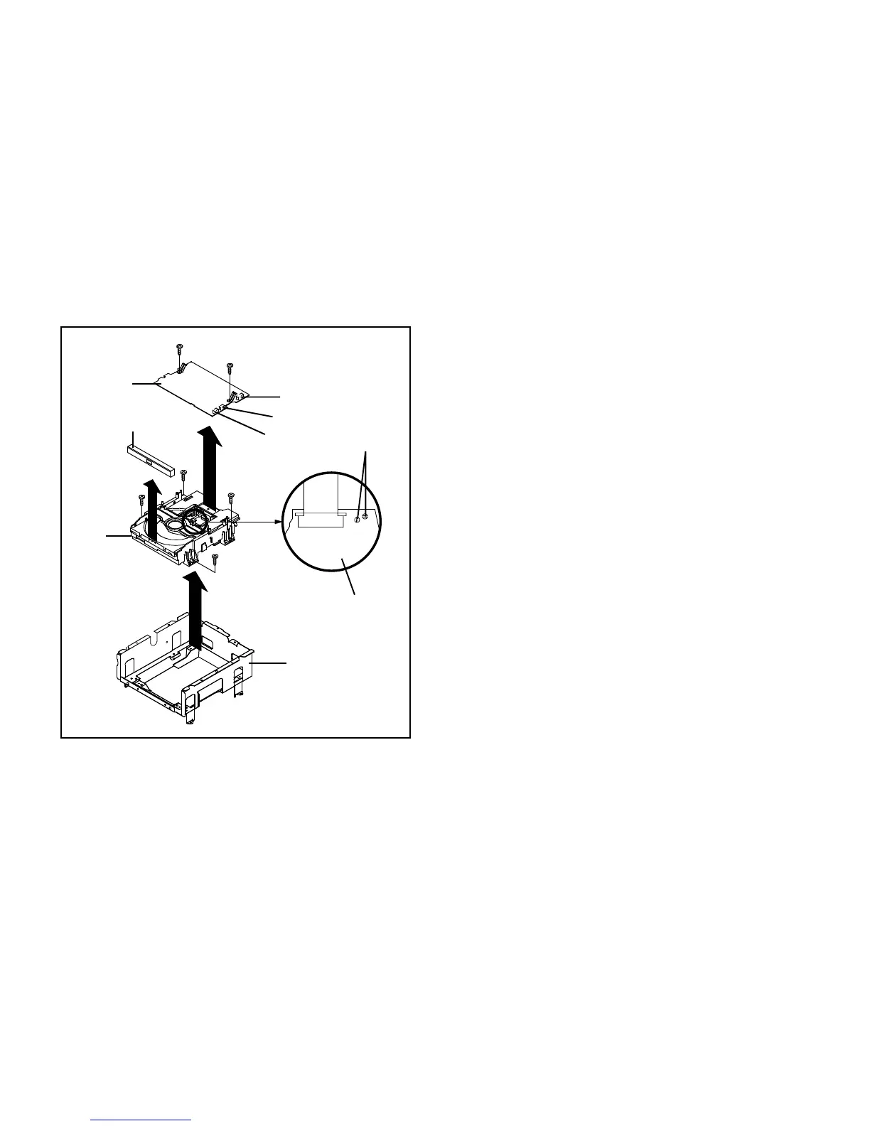
Short circuit the position shown in Fig. 1-5 using a
soldering iron. If you remove the DVD Deck with no
soldering, the Laser may be damaged.
Unlock the 2 supports 1.
Remove the Front Tray Plate in the direction of arrow (A).
Remove the 4 screws 2.
Remove the DVD Deck in the direction of arrow (A).
Disconnect the following connectors:
(CP2301, CP2302 and CP2303).
Remove the 2 screws 3.
Remove the DVD PCB in the direction of arrow (B).
1-5: DVD PCB/DVD DECK (Refer to Fig. 1-5)
Fig. 1-5
Deck CD
Deck Angle
Short circuit using a
soldering iron.
Pick Up PCB
(C)
(A)
(B)
(3)
(3)
Front Tray Plate
CP2301
CP2302
CP2303
NOTE
Before your operation, please read “PREPARATION OF
SERVICING”.
Use the Lead Free solder.
Manual soldering conditions
• Soldering temperature: 350 ± 5˚C
• Soldering time: Within 2 seconds
• Soldering combination: Sn-3.0Ag-0.5Cu
When Soldering/Removing of solder, use the drawing
equipment over the Pick Up Unit to keep the Flux smoke
away from it.
When installing the DVD Deck, remove all the soldering on
the short circuit position after the connection of Pick Up
PCB and DVD PCB connector.
1.
2.
3.
4.
5.
1
3
3
DVD PCB
1
2
2
2
2
 Loading...