DISASSEMBLY INSTRUCTIONS
B2-2
NOTE
1.
2.
3.
4.
In case of the Pulley Motor installation, check if the value
of the Fig. 2-3-B is correct.
When installing the Loading Motor, do it on the position of
Fig. 2-3-C with the following soldering conditions.
Manual soldering conditions
• Soldering temperature: 350 ± 5˚C
• Soldering time: Within 4 seconds
• Soldering combination: Sn-3.0Ag-0.5Cu
When installing the Loading Motor PCB Ass'y, install it
correctly as Fig. 2-3-C.
In case of the Loading Motor PCB Ass'y installation, hook
the wire on the Traverse Ass'y as shown Fig. 2-3-C.
Fig. 2-3-B
7.0 ± 0.1mm
Safety surface for pressing
of the insert.
Loading Motor
Pulley Motor
Fig. 2-3-C
Rack Loading
AB
The Lever should be position
between A and B.
Check Hook
2-4: RACK LOADING/GEAR MAIN/GEAR PULLEY
(Refer to Fig. 2-4-A)
1.
2.
3.
Press down the catcher 1 and slide the Rack Loading.
Unlock the support 2 and remove the Gear Pulley.
Remove the Gear Main.
Loading Motor PCB Ass’y
Loading Belt
Pulley Motor
1
Loader Sub Ass’y
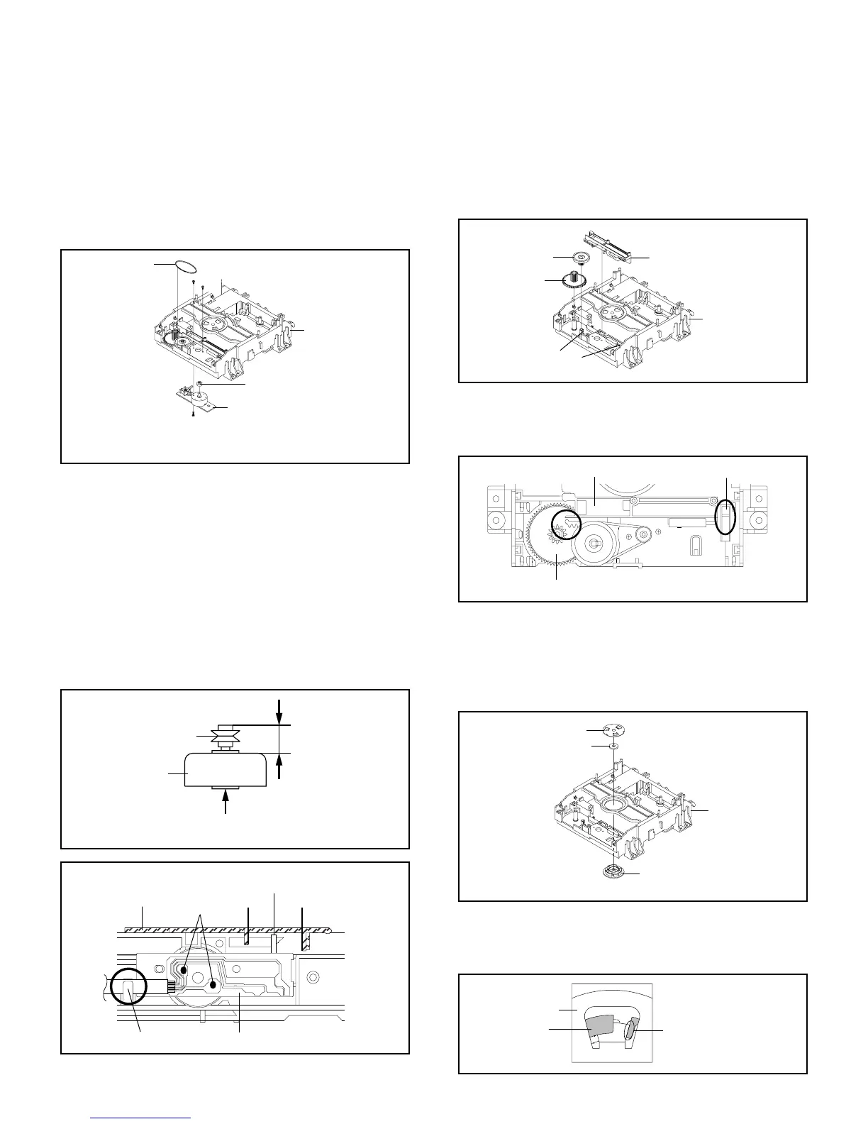
2-3: LOADING MOTOR PCB ASS'Y/ LOADING BELT
(Refer to Fig. 2-3-A)
1.
2.
3.
4.
5.
Remove the Loading Belt.
Remove the screw 1.
Remove the 2 screws 2.
Remove the Loading Motor PCB Ass'y.
Remove the Pulley Motor.
Fig. 2-3-A
2
2
Loading Motor PCB Ass’y
• Screw Torque: 2.5 ± 0.3kgf•cm (Screw 1)
• Screw Torque: 1.0 ± 0.3kgf•cm (Screw 2)
Rack Loading
1
Main Frame
Gear Main
Gear Pulley
2
Fig. 2-4-A
Fig. 2-4-B
NOTE
1. In case of the Rack Loading installation, do not mesh it
to the Gear Main as shown the Fig. 2-4-B.
Check Hook
Gear Main
Rack Loading
2-5: CLAMPER ASS'Y (Refer to Fig. 2-5-A)
Press the Clamper and rotate the Plate Clamper
clockwise, then unlock the 3 supports 1.
Remove the Clamper Plate, Magnet Clamper and
Clamper.
1.
2.
Plate Clamper
Magnet Clamper
Fig. 2-5-A
Main Frame
Clamper
1
1
1
NOTE
1. In case of the Clamper Ass'y installation, install correctly
as Fig. 2-5-B.
Fig. 2-5-B
No gap
Plate Clamper
Clamper
Soldering

 Loading...