Do you have a question about the Toshiba MM-A0224HT and is the answer not in the manual?
Safety notes to be read before installing the unit.
Details of system components including outdoor and indoor units.
Specifies the environmental conditions under which the unit operates.
Explains the naming convention for outdoor and indoor unit models.
Details the possible combinations of outdoor and indoor units.
Lists limitations and rules for combining units.
Describes the priority setting for heating and cooling modes.
Explains different branching configurations like line, header, and combined.
Covers key features like compact design, large capacity, advanced communication, and intelligent control.
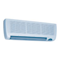
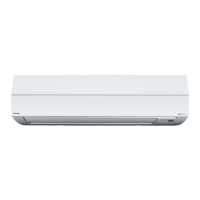
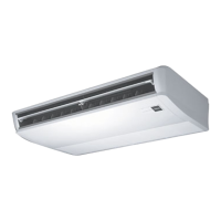
Lists various indoor unit types, models, and their capacities.
Details specifications for different outdoor unit models and their components.
Provides construction details and dimensions for indoor units.
Construction details and dimensions for the slim duct indoor unit.
Construction details and dimensions for 4-way cassette indoor units.
Electrical wiring diagrams for various outdoor unit models.
Wiring diagrams specific to fixed-speed outdoor units.
Wiring diagrams for built-in duct indoor units.
Systematic drawing of refrigerant piping for inverter units.
Refrigerant piping diagram for fixed-speed units.
Shows refrigerant flow for combined units in cooling mode.
Illustrates refrigerant flow during inverter failure backup.
Schematic of the refrigeration cycle for indoor units.
Explains control logic for outdoor units including operation start/stop and thermostat control.
Details the function and control of Pulse Motor Valves.
Explains cooling and heating fan control mechanisms.
Describes controls to prevent oil reduction in compressors.
Explains the process for recovering oil and refrigerant.
Details controls for release valves (SV2) for gas balance and pressure release.
Explains how high pressure affects fixed-speed compressor operation.
Describes the control for heating compressor windings to prevent refrigerant stagnation.
Explains the control logic for the crank case heater.
Details controls managed by the Inverter Package Drive Unit (IPDU).
Explains the defrost operation logic and conditions.
Describes how to prevent cold drafts during heating operation.
Explains the process to remove residual heat from the indoor unit heat exchanger.
Provides additional cautions related to cooling in low temperatures and PMV operation.
Details control logic for indoor units like power reset, operation selection, and room temperature control.
Explains how to interpret system information displayed on rotary switches.
Details the data displayed on outdoor units via switches and push-buttons.
Information on displaying cycle data for outdoor units.
Describes LED displays on the indoor unit's PC board.
Explains how error codes and statuses are shown on the remote controller.
Details the manual control function for PMVs on indoor units.
Describes factory default switch settings for indoor units.
Detailed tables for DIP switch (SW02) network address setup.
Explains how to read check codes and use remote controller buttons.
Details the 7-segment display and filter status indicators.
Explains diagnostic codes for remote controller, indoor unit, and outdoor IPDU.
Provides a diagnostic procedure for water overflow alarms.
Diagnostic steps for indoor fan motor issues.
Diagnostic steps for general indoor unit alarms.
Diagnostic procedure for current detection circuit errors.
Diagnostic steps for TE1 sensor faults.
Diagnostic procedure for Extension IC/EEPROM issues.
Diagnostic steps for compressor related alarms.
Diagnostic procedure for compressor breakdown alarms.
Diagnostic steps for inverter high-pressure switch system alarms.
Diagnostic procedure for inverter IOL (Inner Overload) operation alarms.
Diagnostic steps for fixed-speed IOL/OL system alarms.
Diagnostic procedure for communication failures between indoor and outdoor units.
Diagnostic steps for address consistency issues.
Diagnostic procedure for BUS communication alarms.
Diagnostic procedure for BUS communication alarms.
Diagnostic steps for indoor remote controller communication issues.
Diagnostic procedure for indoor unit miswiring or misconnection.
Diagnostic steps for indoor PMV blockage.
Diagnostic procedure for TD1 sensor faults.
Diagnostic steps for TD2 sensor faults.
Diagnostic procedure for TS1 sensor faults.
Diagnostic steps for TD1 discharge temperature alarms.
Diagnostic procedure for TS condition gas leak detection.
Diagnostic steps for Pd sensor alarms.
Diagnostic procedure for pressure sensor connection issues.
Diagnostic procedure for TD1 condition gas leak detection.
Diagnostic steps for abnormal power phase order.
Diagnostic procedure for Ps sensor alarms.
Diagnostic steps for indoor outside input alarms and interlocks.
Diagnostic procedure for indoor pressure sensor alarms.
Diagnostic steps for TD2 discharge temperature alarms.
Diagnostic procedure for Mg-SW protective operation.
Diagnostic steps for low-pressure protective operation.
Diagnostic procedure for master outdoor unit setup alarms.
Diagnostic procedure for server outdoor unit alarms.
Diagnostic steps for TH sensor alarms.
Diagnostic procedure for TK1 sensor alarms.
Diagnostic steps for TK2 sensor alarms.
Diagnostic procedure for TK3 sensor alarms.
Diagnostic procedure for low oil level detection protection.
Diagnostic steps for TK1 temperature detection circuit alarms.
Diagnostic procedure for TK2 temperature detection circuit alarms.
Diagnostic steps for heat sink overheat alarms.
Diagnostic procedure for oil level detection circuit blockage.
Diagnostic steps for oil level detection circuit leakage.
Diagnostic procedure for outdoor refrigerant leakage.
Diagnostic steps for undefined indoor unit addresses.
Diagnostic procedure for undefined outdoor unit addresses.
Diagnostic steps for fixed-speed high-pressure SW system alarms.
Diagnostic procedure for inverter IOL (Inner Overload) operation alarms.
Diagnostic steps for fixed-speed IOL/OL system alarms.
Explains the 7-segment display on the outdoor unit's interface P.C. board.
Outlines emergency operation procedures when a compressor fails.
Details backup procedures when a fixed-speed unit fails.
Simple method for emergency backup operation during cooling season.
Explains how to forcibly implement oil level detection via switches.
Detailed procedure for performing refrigerant pipe leak tests.
Procedure for vacuuming the refrigerant system after installation.
Calculation and method for adding refrigerant.
Reference chart for additional refrigerant charging amounts.
Outlines the general procedure and checklist for trial operation.
Checks related to power supply and initial setup before trial operation.
Procedure for checking the operation of the fan during trial operation.
Detailed steps for checking cooling operation during trial run.
Explains the automatic addressing process between units.
Overview of service support functions for trial operation.
Function to collectively change indoor units to trial cooling mode.
Function to collectively start/stop indoor units.
Function to individually start/stop indoor units.
Procedures for clearing alarms from remote controller and outdoor unit PC board.
How to clear alarms by resetting power sources.
Procedure to identify remote controllers connected to outdoor units.
Manual full open function for PMVs in indoor units.
Forced opening/closing of PMVs in outdoor units.
Exploded view and parts list for outdoor units.
Detailed part numbers and descriptions for specific outdoor units.
Detailed part numbers and descriptions for MM-A0160HX outdoor unit.
Exploded view of electrical components for outdoor units.
Exploded view and parts list for built-in duct indoor units.
Exploded view and parts list for built-in slim duct indoor units.
Exploded view and parts list for 4-way cassette indoor units.
Exploded view and parts list for 4-way cassette indoor units.
| Brand | Toshiba |
|---|---|
| Model | MM-A0224HT |
| Category | Air Conditioner |
| Language | English |