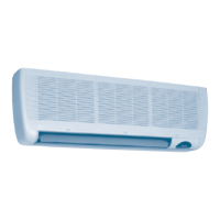
Do you have a question about the Toshiba MM-A0280HX and is the answer not in the manual?
Important safety instructions and warnings for unit installation and operation.
Specifications and models for various outdoor units.
Details on combining outdoor units for multi-split systems.
Types and specifications of branching and header joints for refrigerant piping.
Defines the operational temperature and humidity ranges for the unit.
Specifies the number of units and capacity range for combinations.
Defines limitations and specific rules for unit combinations.
Explains the priority settings for heating and cooling modes.
Describes different branching configurations for refrigerant piping.
Highlights the space-saving and maneuverability features of the unit.
Details the maximum system capacity achievable with the MMS.
Explains the simplified wiring and automatic address configuration.
Features comprehensive troubleshooting codes for quick problem identification.
Details the unit's capability for significant vertical pipe runs.
Covers the flexibility of combining various indoor units with the outdoor unit.
Explains how intelligent controls optimize capacity and maintain comfort.
Lists and describes various indoor unit models and their specifications.
Provides detailed dimensional drawings and piping connection points for outdoor units.
Dimensional drawings for various indoor unit types.
Presents electrical wiring diagrams for outdoor units.
Wiring diagram for fixed-speed outdoor units.
Electrical wiring diagrams for various indoor unit types.
Systematic piping diagrams for inverter outdoor units.
Systematic refrigerant piping diagrams for fixed-speed outdoor units.
Systematic refrigerant piping diagrams for the 6HP fixed-speed unit.
Illustrates refrigerant flow during normal cooling operation of combined units.
Refrigerant piping diagram for emergency operation when inverter unit fails.
Refrigerant piping diagram for emergency operation when fixed-speed unit fails.
Procedure for recovering refrigerant when an outdoor unit fails.
Schematic diagram of the refrigeration cycle for indoor units.
Explains operational logic and control sequences for outdoor units.
Details operational logic and control functions for indoor units.
Information on system status and data displayed via rotary switches on outdoor units.
Details LED indicators on indoor unit PC boards and remote controller displays.
Explains how to read check codes and status from the remote controller.
Lists error codes and their corresponding causes for system diagnosis.
Flowcharts for diagnosing and resolving specific error check codes.
Details the function and outline of key system components like valves, sensors, and motors.
Procedures for backup operation when a compressor or outdoor unit fails.
Steps for setting backup operation when a compressor fails.
Procedure for backup operation when the inverter unit fails.
Details on how to manually initiate oil level detection for the outdoor unit.
Procedure for performing leak tests on the refrigerant piping system.
Calculates and explains how to add refrigerant based on pipe length and size.
Provides a chart for calculating additional refrigerant charging amounts.
Outlines the steps for conducting a trial operation of the system.
Explains the automatic addressing process between outdoor and indoor units.
Functions to support trial operations and system checks via interface PC board.
Enables controlling indoor units from the outdoor unit via switch operation.
Procedures for clearing system alarms and resetting operations.
Covers manual FULL OPEN/FULL CLOSE functions for PMV in indoor and outdoor units.
Diagrams and part numbers for outdoor unit components.
Diagrams and part numbers for indoor unit components.
Information on further resources and contact details.
| Brand | Toshiba |
|---|---|
| Model | MM-A0280HX |
| Category | Air Conditioner |
| Language | English |


