25
Nominal dia.
Max. interval (m)
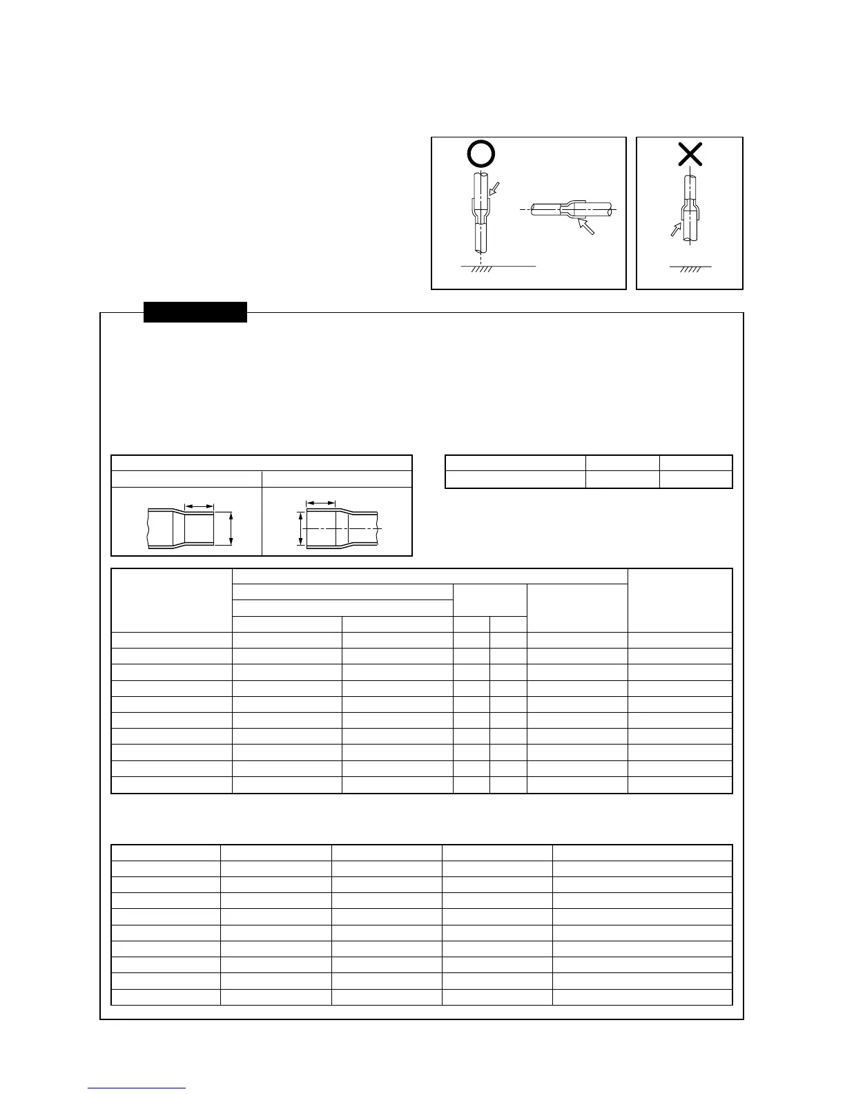
5-10. Brazing Work
1. Brazing work should be performed downwards
or sideways. Avoid brazing upwards (in order to
avoid incomplete brazing). (Recommendation)
2. Always used the specified piping materials for
liquid pipes and gas pipes, and make sure that
they are installed in the proper direction and at
the proper angle.
3. The “nitrogen gas blow” method should be used
when brazing.
CAUTIONS
1. Pay attention to fire prevention concerns. (Take preventative measures in the area where brazing work is to
be performed, such as keeping a fire extinguisher or water handy.)
2. Be careful not to burn yourself.
3. Make sure that any gaps between pipes and couplings are appropriate. (Do not miss brazing any joints.)
4. Make sure that pipes are adequately supported.
• The following table provides basic guidelines for the interval between supports for horizontal copper pipe.
Interval between supports for copper pipe
• Avoid securing copper pipes with metal brackets
directly.
* Gas brazing of refrigerant pipes must be performed by personnel qualified to do so under local ordinances.
Minmum wall thickness for R410A application
Brazing material
Brazing
material
Lateral direction
Brazing
material
(Direction downward) (Direction upward)
(Recommended brazing)
Coupling size of brazed pipe
Standard outer dia. of
connected copper pipe
6.35
9.52
12.70
15.88
19.05
22.22
28.58
34.92
38.10
41.28
External size Internal size
Standard outer dia. (Allowable difference)
CF
6.35 (±0.03) 6.45 ( )
9.52 (±0.03) 9.62 ( )
12.70 (±0.03) 12.81 ( )
15.88 (±0.03) 16.00 ( )
19.05 (±0.03) 19.19 ( )
22.22 (±0.03) 22.36 ( )
28.58 (±0.04) 28.75 ( )
34.90 (±0.04) 35.11 ( )
38.10 (±0.05) 38.31 ( )
41.28 (±0.05) 41.50 ( )
Min. depth
of insertion
KG
76
87
98
98
11 10
11 10
13 12
14 13
15 14
15 14
Oval value
0.06 or less
0.08 or less
0.10 or less
0.13 or less
0.15 or less
0.16 or less
0.20 or less
0.25 or less
0.27 or less
0.28 or less
Min. thickness
of coupling
0.50
0.60
0.70
0.80
0.80
0.82
1.00
1.20
1.26
1.35
+0.04
–0.02
+0.04
–0.02
+0.04
–0.02
+0.04
–0.02
+0.03
–0.03
+0.03
–0.03
+0.06
–0.02
+0.04
–0.04
+0.08
–0.02
+0.08
–0.02
Connected section
(Unit: mm)
Connected section
External size Internal size
20 or less 25 to 40
1.0 1.5
Soft (Coil)
¡
¡
¡
¡
NG
NG
NG
NG
NG
Hard or Half hard
¡
¡
¡
¡
¡
¡
¡
¡
¡
OD (Inch)
1/4
3/8
1/2
5/8
3/4
7/8
1.1/8
1.3/8
1.5/8
OD (mm)
6.35
9.52
12.70
15.88
19.05
22.20
28.58
34.92
41.28
Minium wall thickness
0.80
0.80
0.80
1.00
1.00
1.00
1.00
1.10
1.25
K
ØC
G
ØF
 Loading...