C
Chad EvansAug 13, 2025
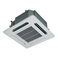
How to clean a contaminated filter in a Toshiba Air Conditioner?
- JJason CardenasAug 13, 2025
If the filter of your Toshiba Air Conditioner is contaminated, wash it with water to remove the contamination.
How to clean a contaminated filter in a Toshiba Air Conditioner?
If the filter of your Toshiba Air Conditioner is contaminated, wash it with water to remove the contamination.
What to do if the filter of my Toshiba MMU-AP0122H Air Conditioner is damaged?
If the filter of your Toshiba Air Conditioner is damaged, replace it with a new one.
What to do if there is dust/dirt clogging in the drain pan of my Toshiba MMU-AP0122H Air Conditioner?
If the drain pan of your Toshiba Air Conditioner is clogged with dust or dirt, clean the drain pan. Also, make sure to check the downward slope to ensure smooth drainage.
How to clean dust/dirt clogging in the heat exchanger of Toshiba Air Conditioner?
If the heat exchanger in your Toshiba Air Conditioner is clogged with dust or dirt, wash it to remove the blockage.
How to clean a contaminated fan in a Toshiba MMU-AP0122H Air Conditioner?
If the fan of your Toshiba Air Conditioner is contaminated, brush or wash it to remove the contamination.
What to do if ornamental panel or louvers of Toshiba MMU-AP0122H Air Conditioner are contaminated?
If the ornamental panel or louvers of your Toshiba Air Conditioner are contaminated, wash them. Alternatively, you can apply a repair coating.
What to do if air inlet/outlet grilles of my Toshiba MMU-AP0122H are deformed or damaged?
If the air inlet or outlet grilles of your Toshiba Air Conditioner are deformed or damaged, fix or replace them.
What to do if Toshiba MMU-AP0122H fan has vibration or balance issues?
If the fan of your Toshiba Air Conditioner has terrible vibration or balance issues, replace it.
| Cooling Capacity (kW) | 3.5 |
|---|---|
| Heating Capacity (kW) | 4.0 |
| Power Source | 220-240V, 50Hz |
| Refrigerant | R410A |
| Indoor Unit Weight | 9 kg |
Important safety precautions for troubleshooting, repair, and general handling of the unit.
Detailed technical specifications for the indoor unit models, including capacity, dimensions, and electrical characteristics.
Diagrams illustrating the external dimensions, connection ports, and installation clearances of the indoor unit.
Detailed wiring diagram for the 4-Way Air Discharge Cassette type indoor unit, showing connections between components.
Lists the rating and names of various parts used in the indoor unit, with model compatibility.
Diagram illustrating the air conditioner's refrigerating cycle and outlining the functions of key components.
Outlines the control specifications for the air conditioner, including power reset behavior and operation mode selection.
Block diagrams detailing the internal control circuit configuration of the indoor unit, including remote controller and network connections.
Procedure for setting various functions in the indoor unit using a wired remote controller, detailing item codes and data.
Details the remote location ON/OFF control box and its wiring for controlling unit operation remotely.
Explains how to control the ventilating fan from the remote controller for systems with air-to-air heat exchangers.
Describes the function to prevent unintended operation or stop, controlled by external contacts or card switches.
Details the function to force thermostat-OFF operation when the relay is turned on.
Manual procedure for setting indoor unit addresses and group configurations from the remote controller.
Procedure for setting various functions and parameters in the indoor unit using the remote controller.
Instructions on how to check and verify indoor unit numbers and their positions within the system using the remote controller.
Steps to change indoor unit addresses manually from the remote controller, ensuring no duplication.
Methods for clearing detected errors from the remote controller, covering both outdoor and indoor unit errors.
Guide to using the remote controller's monitoring function to check sensor temperatures and operating statuses.
Guidelines and warnings regarding installation location, electrical wiring, and potential noise/vibration issues.
Information on accessory parts and general safety precautions to be followed during installation work.
Criteria and recommendations for selecting the appropriate installation location, considering safety and operational factors.
Specifies the required space around the unit for installation, servicing, and proper ventilation.
Details on external views, ceiling opening, hanging bolts, and related installation procedures and components.
Provides a summary of common troubles, check items, and troubleshooting procedures for identifying and resolving issues.
Explains how to use self-diagnosis functions on remote controllers and outdoor units to identify error codes.
Lists check codes detected by indoor units and their corresponding main defective positions and descriptions.
Lists check codes detected by outdoor units, including IPDU errors, and their corresponding main defective positions and descriptions.
Guide to interpreting check codes and error histories displayed on wired remote controllers for troubleshooting.
Explains how to interpret error codes displayed on the wireless remote controller's receiving unit.
Instructions for detaching and attaching common parts like suction grilles and electric parts covers.
Procedure for removing and installing the ceiling panel and associated adjustment corner caps.
Procedures for detaching and installing key components such as the P.C. board, fan motor, drain pump, and heat exchanger.
Steps for detaching and attaching float switch assembly and drain pan, ensuring proper water management.
Procedures for replacing the indoor unit P.C. board, covering data backup, restoration, and setup.
Steps to read out setting data from the EEPROM using the remote controller before P.C. board replacement.
Procedure for writing setting data to the EEPROM, including model type, capacity, and address settings.
Exploded diagrams and parts list for MMU-AP0092H, AP0122H, AP0152H, AP0182H, and AP0242H models.
Exploded diagrams and parts list for MMU-AP0272H, AP0302H, AP0362H, AP0482H, and AP0562H models.
Parts list and exploded view for RBC-U31PG/PGS and RBC-AX31U remote controllers.