E
Elizabeth DavisAug 13, 2025
How to clean a contaminated filter in a Toshiba Air Conditioner?
- SShane HollowayAug 13, 2025
If the filter of your Toshiba Air Conditioner is contaminated, wash it with water to remove the contamination.
How to clean a contaminated filter in a Toshiba Air Conditioner?
If the filter of your Toshiba Air Conditioner is contaminated, wash it with water to remove the contamination.
What to do if the filter of my Toshiba MMU-AP0182H is damaged?
If the filter of your Toshiba Air Conditioner is damaged, replace it with a new one.
What to do if there is dust/dirt clogging in the drain pan of my Toshiba Air Conditioner?
If the drain pan of your Toshiba Air Conditioner is clogged with dust or dirt, clean the drain pan. Also, make sure to check the downward slope to ensure smooth drainage.
How to clean dust/dirt clogging in the heat exchanger of Toshiba MMU-AP0182H Air Conditioner?
If the heat exchanger in your Toshiba Air Conditioner is clogged with dust or dirt, wash it to remove the blockage.
How to clean a contaminated fan in a Toshiba MMU-AP0182H Air Conditioner?
If the fan of your Toshiba Air Conditioner is contaminated, brush or wash it to remove the contamination.
What to do if ornamental panel or louvers of Toshiba MMU-AP0182H Air Conditioner are contaminated?
If the ornamental panel or louvers of your Toshiba Air Conditioner are contaminated, wash them. Alternatively, you can apply a repair coating.
What to do if air inlet/outlet grilles of my Toshiba MMU-AP0182H Air Conditioner are deformed or damaged?
If the air inlet or outlet grilles of your Toshiba Air Conditioner are deformed or damaged, fix or replace them.
What to do if Toshiba Air Conditioner fan has vibration or balance issues?
If the fan of your Toshiba Air Conditioner has terrible vibration or balance issues, replace it.
| Brand | Toshiba |
|---|---|
| Model | MMU-AP0182H |
| Category | Air Conditioner |
| Language | English |
Details safety precautions for R410A refrigerant, including pressure and oil changes.
Provides specific guidelines for handling R410A during installation and service work.
Specifies recommended copper pipes and flare nuts for R410A refrigerant systems.
Lists tools specifically required for R410A refrigerant systems and their interchangeability.
Lists general tools also necessary for R410A installations, which can be used with R22.
Details the technical specifications for the indoor unit, including dimensions, capacity, and electrical characteristics.
Provides the specific wiring diagram for the 4-Way Air Discharge Cassette Type models.
Lists the ratings and specifications for various parts used in the air conditioner units.
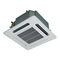
Identifies and labels the different parts of the air conditioner unit for reference.
Explains the meaning of various indicators and symbols on the remote controller display.
Details the purpose and operation of each button on the remote controller for various functions.
Controls essential functions like starting/stopping, mode selection, and temperature adjustment.
Adjusts air volume, louver direction, and swing settings for optimal comfort.
Manages timer settings, filter reset, and test run operations for maintenance.
Explains how to adjust wind direction and initiate/stop louver swing.
Explains how to select individual indoor units for setting wind direction.
Guides on setting individual louver directions for each discharge port.
Explains how to lock louvers and use the remote controller sensor for temperature adjustment.
Advises on suitable installation locations and avoiding places with potential hazards.
Outlines critical safety precautions for electrical wiring, grounding, and leakage breakers.
Step-by-step instructions for cleaning the air filters and the unit panels.
Instructions for cleaning the discharge louver and performing periodic checks.
Essential checks before operation and details on heating capacity and performance.
Covers protective devices, power failures, operating conditions, and multi-system controls.
Addresses symptoms related to compressor, fan, unit operation, and cooling/warming issues with potential causes.
Important safety advice and actions to take when specific conditions occur, including when to contact a dealer.
Explains how to confirm errors and check history using the remote controller's display.
Lists parts included with the unit for installation purposes.
Identifies parts that are sold separately and required for installation.
Specific safety guidelines for installing units using R410A refrigerant.
Covers safe procedures for disconnecting power and choosing a safe installation location.
Details required space, ceiling height considerations, and installation advice.
Explains how to select discharge directions and manage airflow based on room conditions.
Covers general installation requirements, external views, and ceiling preparation.
Details the process of installing hanging bolts and securing the ceiling structure.
Provides specific steps for creating ceiling openings and installing hanging bolts.
Instructions for installing the ceiling panel and remote controller, including wireless setup.
Covers flexible hose usage, connecting drain pipes, and essential requirements for proper drainage.
Details procedures for drain-up piping and verifying drainage performance.
Outlines standards for refrigerant piping, including pipe size, length, and evacuation steps.
Details critical steps for flaring pipes and important considerations during piping work.
Explains proper methods for tightening pipe connections and connecting to the outdoor unit.
Covers procedures for airtight testing, air purging, and applying thermal insulation to pipes.
Details specifications for power supply and control wiring, including safety precautions.
Explains communication line types, wire connections, and requirements for secure wiring.
Covers thermal insulation for wiring ports and important wiring connection precautions.
Details wiring for remote controllers, inter-unit communication, and wiring examples.
Covers wiring for flow selector units, address setup, and ceiling panel wiring.
Explains how to change settings for applicable controls, including filters and high ceiling installation.
Covers settings when using a wireless remote and adjusting filter sign lighting time.
Details how to select horizontal wind direction and set up swing types for louvers.
Explains dual swing, cycle swing modes, and how to lock louver positions.
Describes using the remote controller sensor and managing group control operations.
Covers pre-test run checks and the procedure for executing test runs with both wired and wireless remotes.
Step-by-step instructions for cleaning the air filters and the unit panels.
Instructions for cleaning the discharge louver and performing periodic checks.
Provides an overview of troubleshooting steps and how to check error history via the remote controller.
Lists indoor unit error codes, their detected positions, main defective parts, and descriptions for diagnosis.
Details error codes detected by the TCC-LINK central control device, including communication and address issues.
Outlines the control specifications for the air conditioner's operation modes and temperature control.
Explains advanced room temperature control, automatic capacity adjustment, and cooling/heating exchange logic.
Details how air speed is selected based on room and set temperatures in COOL and HEAT modes.
Covers air speed selection for 4-way cassette types and preventing cold air discharge.
Explains freeze prevention control and refrigerant oil recovery procedures.
Details heating refrigerant recovery, intermittent operation compensation, drain pump, HA control, and filter sign display.
Explains READY/HEAT READY indicators and operational modes for AI-NET and TCC-LINK central control.
Details how to set louver positions and configure swing operations for 4-way cassette units.
Guides on setting air direction for each louver individually.
Explains the selection of different swing modes (Standard, Dual, Cycle).
Explains how to lock louvers in fixed positions, preventing swing.
Describes the operation of the DC motor and potential error conditions.
Notes that the Save Operation function is not provided for this model series.
Details the internal control circuit configuration for the indoor unit.
Provides a block diagram of the indoor unit's controller circuit.
Explains how to connect a wired remote controller to the indoor unit's control circuit.
Guides on connecting the wireless remote controller kit to the indoor unit.
Instructions for connecting both wired and wireless remote controllers simultaneously.
Illustrates and labels the components on the indoor unit's P.C. board.
Details the steps for performing cooling and heating test runs using wired and wireless remotes.
Explains how to check indoor unit operation directly using the P.C. board, bypassing the remote controller.
Lists specifications for optional connectors on the indoor unit's P.C. board.
Guides on setting various functions for the indoor unit using a wired remote controller.
Provides a list of function codes (DN) and their corresponding settings for applied controls.
Explains settings for high ceiling installations and built-in filters.
Covers timer setup using a wired remote and configuring indoor unit capacity.
Details the function and wiring of the remote ON/OFF control box.
Explains how to control the ventilating fan using a wired remote controller and its wiring.
Describes the function, control items, operation, and wiring for leaving-ON prevention.
Details the power peak-cut function that forces thermostat-OFF operation.
Step-by-step guide for manually setting indoor unit addresses using the remote controller.
Procedures to check the recognized indoor unit addresses and their positions in group control.
Step-by-step guide for setting various functions for the indoor unit using the remote controller.
Describes how to check all unit numbers and their piping positions using a wired remote controller.
Explains how to change indoor unit addresses from an arbitrary wired remote controller.
Instructions on how to clear errors for both outdoor and indoor units using the remote controller.
Explains how to use the remote controller's monitoring function to check sensor temperatures and operating status.
Provides a summary of common troubles, applicable models, required tools, and troubleshooting steps.
Lists indoor unit error codes, their detected positions, main defective parts, and descriptions for diagnosis.
Details error codes detected by remote and central controllers, including their causes.
Lists outdoor unit error codes, detected positions, main defective parts, and descriptions for troubleshooting.
Lists IPDU errors, their causes, and check items for S-MMS standard outdoor units.
Explains how to confirm errors and check history using the remote controller's display.
Details error confirmation and history check procedures using a central remote controller.
Lists error codes displayed on the wireless receiver unit and their corresponding causes.
Describes lamp indications for test run and COOL/HEAT disagreement scenarios.
Lists check codes for Super Modular Multi systems, including detected positions and error details.
Details error codes related to IPDU communication, sensors (TCJ, TC2, TC1, TD1, TD2, TE1, TL, TO, TA, TS1, TH), and their causes.
Lists error codes for compressor breakdown, lock, MG-SW, OCR, and current detection circuits.
Details error codes for compressor case thermostat operation and oil level detection issues.
Covers errors related to compressor thermo, address, and capacity settings.
Details errors related to unit addresses, capacity, FS unit system, IPDU, and interlock conditions.
Lists error codes for indoor fan motor, discharge temperature (TD1), high-pressure SW, and heat sink overheat.
Covers errors related to outdoor liquid back detection, gas leak, discharge temperature (TD2), 4-way valve, and high-pressure operation.
Details errors related to outdoor fan IPDU, G-Tr short-circuit, compressor position detection, and other indoor unit errors.
Lists errors detected by the TCC-LINK central control device, including communication and address issues.
Displays resistance-temperature curves for indoor TA, TC1, TC2, and TCJ sensors.
Step-by-step instructions for removing and installing the suction grille.
Procedures for removing and installing the electric parts cover.
Further steps for attaching the electric parts cover.
Instructions for detaching and attaching the adjust corner cap.
Step-by-step guide for removing and installing the ceiling panel.
Procedures for removing and installing the main control P.C. board.
Instructions for removing and installing the drain cap, including proper orientation.
Step-by-step guide for removing and installing the fan motor, including torque specifications.
Further steps for attaching the fan motor and its components, including wiring.
Procedures for removing and installing the drain pump and its associated parts.
Instructions for removing and installing the float switch assembly.
Procedures for removing and installing the drain pan and its related components.
Steps for removing and installing the PMV motor, including torque control.
Detailed instructions for removing and installing the heat exchanger, including refrigerant recovery.
Explains the procedure for replacing the indoor unit's P.C. board.
Guides on how to read and record setting data from the EEPROM before replacing the P.C. board.
Details the process of replacing the P.C. board and configuring system settings.
Instructions for writing setting data to the EEPROM after the P.C. board has been replaced.