– 8 –
15-EN 16-EN
6 Installation of the outdoor unit
WARNING
•
Be sure to install the outdoor unit in a place able to bear its weight.
If strength is insuffi cient, the unit may fall down resulting in human injury.
•
Perform specifi ed installation work to protect against strong wind and earthquakes.
If the outdoor unit is imperfectly installed, an accident by falling or dropping may be caused.
CAUTION
•
Drain water is discharged from the outdoor unit. (Especially while heating)
Install the outdoor unit in a place with good drainage.
•
For installation, be careful of the strength and level of the foundation so that abnormal sounds (vibration or
noise) are not generated.
REQUIREMENT
Installation in a snowfall area
1. Install the outdoor unit on a higher foundation than the snowfall or set up a stand to install the unit so that
snowfall will not affect the unit.
• Set up a stand higher than the snowfall.
• Apply an angled structure to the stand so that drainage will not be prevented. (Avoid using a stand with a fl at
surface.)
2. Mount a snowfall-hood onto the air intake and the air discharge.
• Leave enough space for the snowfall-hood so that it will not be an obstacle for the air intake and the air
discharge.
Snowfall-hood for air
discharge (locally
procured)
Snowfall-hood for air
discharge
(4 faces)
(locally procured)
Stand
(locally procured)
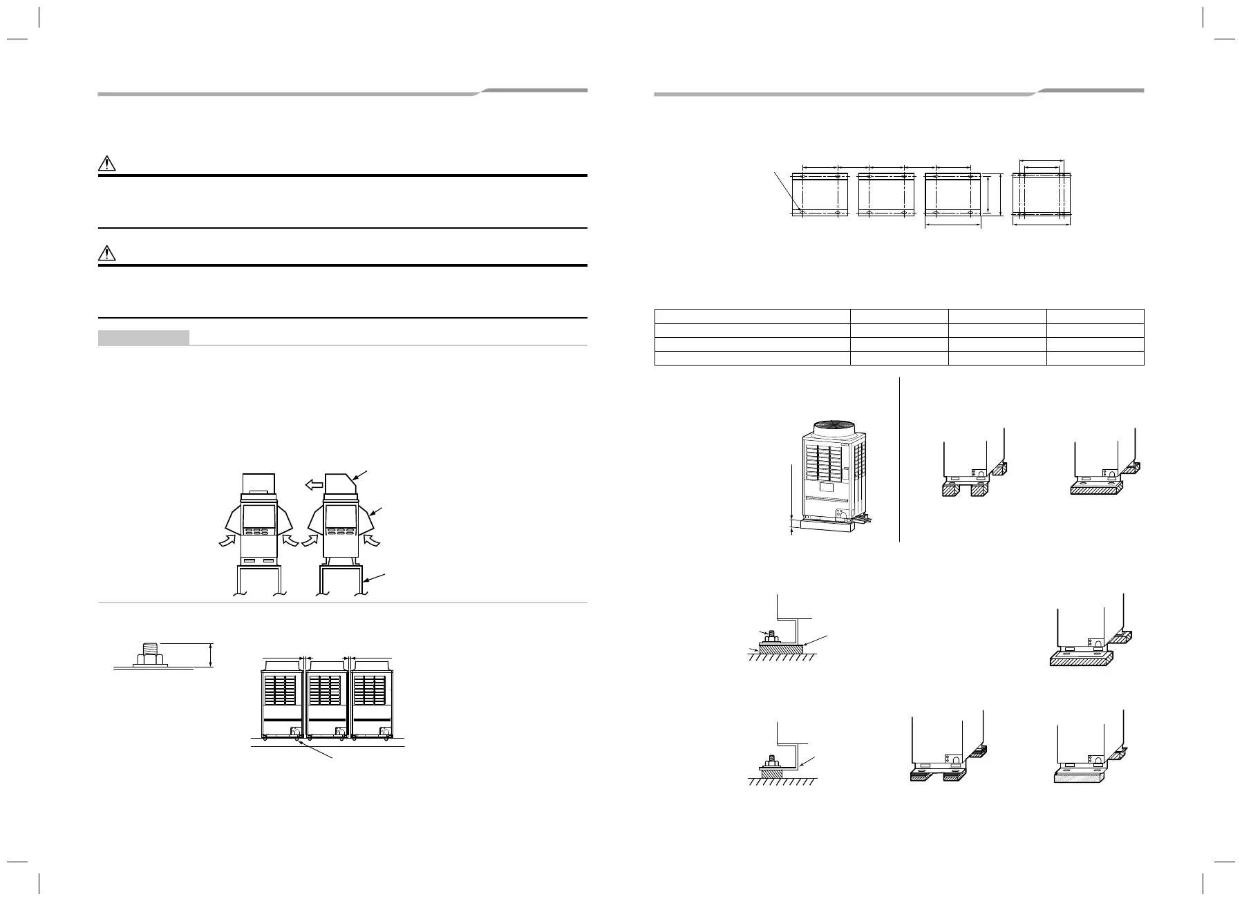
1. To install multiple outdoor units, arrange them with 20mm or more spaces in between.
Fix each outdoor unit with M12 anchor bolts at 4 positions. 20mm projection is appropriate for an anchor bolt.
20
M12 anchor bolt
4 positions/unit
20mm or more 20mm or more
• Anchor bolt positions are as shown below:
A A A
B
755
790
A
C*
B
Continuous hole
(15 x 20 long hole)
*Only MAP14A,
MAP16A, MAP180,
MAP200 type has
holes for additional
strength.
310 or
more
310 or
more
(Unit : mm)
Model type A B C
MAP080*, MAP100*, MAP120* 700 990 –
MAP10A*, MAP12A*, MAP140*, MAP160* 920 1210 –
MAP14A*, MAP16A*, MAP180*, MAP200* 1310 1600 1500
2. When drawing out the refrigerant pipe from the
underside, set the height of the stand to 500mm or
more.
500mm or more
3. Do not use 4 stands on the corner to support the
outdoor unit.
NO GOOD GOOD
4. Mount the vibration-proof rubber (including vibration-proof blocks) so that it fits under the whole clamping leg.
GOOD
NO GOOD NO GOOD NO GOOD
GOOD
Install the vibration-proof
rubber so that the bent part
of the fi xing leg is
grounded.
Anchor bolt
Vibration-proof rubber
The bent part of
the fi xing leg is not
grounded.
1117101401-3_EN.indd 81117101401-3_EN.indd 8 1/12/16 3:18 PM1/12/16 3:18 PM

 Loading...


