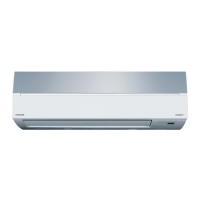
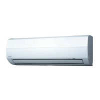
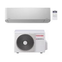
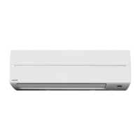
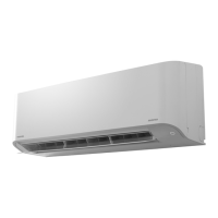
Do you have a question about the Toshiba RAS-09EKH and is the answer not in the manual?
Details cooling and heating capacity in kW and Btu/h for different voltages.
Specifies refrigerant type, volume, and interconnection pipe dimensions.
Guidance on connecting refrigerant pipes to the indoor unit, including drain hose placement.
Steps for cutting and preparing refrigerant pipes using a flaring tool.
Details on correct flaring length, finishing, and avoiding pipe distortion.
Procedure for connecting flare pipes to ensure proper alignment and seal.
Specifies torque values and methods for tightening flare nuts to prevent leaks.
Schematic showing electrical connections between indoor and outdoor units.
Visual representation of the refrigerant path through the system for cooling and heating.
Table detailing pressure, temperature, and fan speed conditions for performance testing.
Diagram illustrating the micro-computer's role in controlling various unit functions.
Detailed description of each button on the remote controller and its function.
Criteria for initiating the defrost cycle, including time and temperature.
Details on the duration and cycles of the defrost operation.
Conditions that cause the defrost operation to end and normal operation to resume.
Basic checks before diagnosing faults, including power supply and cable connections.
Table of block displays indicating self-diagnosis codes and their meanings.
Table for primary judgment of defective operation based on system checks.
Procedure to enter the remote controller's service mode for self-diagnosis.
Procedure to return the remote controller to normal operating mode.
Table correlating check codes, symptoms, and recommended actions.
Flowchart for diagnosing issues when the unit does not operate at all.
Flowchart for diagnosing issues when the compressor and indoor fan do not operate.
Flowchart for checking remote control signal transmission and reception.
Steps to check power supply and identify potential faults on the PC board.
| Brand | Toshiba |
|---|---|
| Model | RAS-09EKH |
| Category | Air Conditioner |
| Language | English |


