Do you have a question about the Toshiba RAS-107SKV-E and is the answer not in the manual?
Safety guidelines for general users regarding power supply and maintenance.
Safety measures for R410A refrigerant installation and servicing.
Warnings regarding high voltage, power disconnection, and grounding.
Detailed technical specifications for indoor and outdoor units.
Graphs showing cooling/heating performance vs. compressor speed.
How cooling/heating capacity varies with outside temperature.
Safety guidelines specific to R410A refrigerant.
Procedures for installing refrigerant piping.
Specifications for copper pipes and joints used with R410A.
Detailed steps and dimensions for flare pipe connections.
Materials, procedures, and flux requirements for brazing pipes.
Steps for recharging refrigerant into the system.
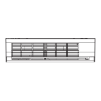
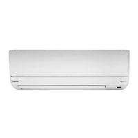
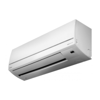
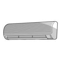
Exploded view and dimensions of the indoor unit.
Exploded view and dimensions of the outdoor unit.
Electrical schematic for the indoor unit.
Electrical schematic for the outdoor unit.
List of electrical components for the indoor unit.
List of electrical components for the outdoor unit.
Schematic showing refrigerant flow and components.
Performance data under various cooling and heating conditions.
Block diagram of the indoor unit's control system.
Block diagram of the outdoor unit's control system.
Overview of the unit's control system and functions.
Explanation of cooling, heating, AUTO, and DRY modes.
Details on controlling the indoor fan speed and operation.
How the unit manages frost removal during heating.
Operation and purpose of the self-cleaning feature.
How to set up and cancel the auto restart feature.
How to operate the unit using the remote controller.
Explanation of all symbols and indicators on the remote display.
Visual guide for installing indoor and outdoor units.
List of parts included or required for installation.
Tools required for installation and servicing.
Detailed steps for installing the indoor unit.
Detailed steps for installing the outdoor unit.
Procedures for connecting refrigerant pipes.
Process for removing air and moisture from the refrigerant circuit.
Steps for connecting electrical wiring.
Normal operating conditions that might be mistaken for faults.
Initial steps for diagnosing faults using indicators and self-diagnosis.
Interpreting error codes indicated by indoor unit LEDs.
Using the remote controller for detailed fault diagnosis.
Diagnosing issues based on specific symptoms like no power.
Troubleshooting communication and wiring issues between units.
Procedures for checking key components like P.C. boards and motors.
Specific tests for sensors, capacitors, and modules.
Procedures for replacing indoor unit components.
Procedures for replacing outdoor unit components.
Exploded view and part numbers for the indoor unit.
Exploded view and part numbers for the outdoor unit.
Diagram showing component locations on the P.C. board.
| Type | Split System |
|---|---|
| Cooling Capacity | 2.5 kW |
| Heating Capacity | 3.2 kW |
| Power Supply | 220-240V, 50Hz |
| Refrigerant | R410A |
| Energy Efficiency Ratio (EER) | 3.21 |
| Coefficient of Performance (COP) | 3.61 |
| Noise Level (Outdoor) | 48 dB(A) |
| Weight (Indoor Unit) | 9 kg |
| Weight (Outdoor Unit) | 28 kg |